没有合适的资源?快使用搜索试试~ 我知道了~
TI-LMK61I2-100M.pdf
需积分: 10 0 下载量 123 浏览量
2022-11-30
22:58:04
上传
评论 4
收藏 734KB PDF 举报
温馨提示
![preview](https://dl-preview.csdnimg.cn/87222257/0001-0915e69fab6b8e40525fbddead6f0931_thumbnail.jpeg)
![preview-icon](https://csdnimg.cn/release/downloadcmsfe/public/img/scale.ab9e0183.png)
试读
22页
TI-LMK61I2-100M.pdf
资源推荐
资源详情
资源评论
![zip](https://img-home.csdnimg.cn/images/20210720083736.png)
![pdf](https://img-home.csdnimg.cn/images/20210720083512.png)
![](https://csdnimg.cn/release/download_crawler_static/87222257/bg1.jpg)
NC OUTN
VDDOE
GND OUTP
1 6
2 5
43
1
2
3
6
5
4
Product
Folder
Order
Now
Technical
Documents
Tools &
Software
Support &
Community
An IMPORTANT NOTICE at the end of this data sheet addresses availability, warranty, changes, use in safety-critical applications,
intellectual property matters and other important disclaimers. PRODUCTION DATA.
English Data Sheet: SNAS676
LMK61E0-050M
,
LMK61E0-155M
,
LMK61E0-156M
,
LMK61E2-100M
,
LMK61E2-125M
LMK61E2-156M
,
LMK61E2-312M
,
LMK61A2-100M
,
LMK61A2-125M
,
LMK61A2-156M
LMK61A2-312M
,
LMK61A2-644M
,
LMK61I2-100M
ZHCSG14D –OCTOBER 2015–REVISED OCTOBER 2017
LMK61XX 高高性性能能超超低低抖抖动动振振荡荡器器
1
1 特特性性
1
• 超低噪声、高性能
– 抖动:Fout > 100MHz 时的典型值为 90fs RMS
– PSRR:–70dBc,强大的电源抗噪性
• 支持的输出格式
– LVPECL 高达 1 GHz
– LVDS 高达 900 MHz
– HSTL 高达 400 MHz
• 总频率容差:±50ppm(LMK61X2) 和 ± 25ppm
(LMK61X0)
• 3.3V 工作电压
• 工业温度范围(-40ºC 至 +85ºC)
• 7mm × 5mm 6 引脚封装,与行业标准 7050 XO 封
装引脚兼容
2 应应用用
• 晶体振荡器、SAW 振荡器或芯片振荡器的高性能
替代产品
• 开关、路由器、网卡、基带装置 (BBU)、服务器、
存储/SAN
• 测试和测量
• 医疗成像
• FPGA,处理器连接
3 说说明明
LMK61XX 是一款超低抖动振荡器,可生成常用的基准
时钟。该器件在出厂前进行了预编程,支持任何基准时
钟频率;支持的输出格式包括 LVPECL(最高
1GHz)、LVDS(最高 900MHz)和 HCSL(最高
400MHz)。内部电源调节功能提供出色的电源纹波抑
制 (PSRR),降低了供电网络的成本和复杂性。该器件
由单个 3.3V ± 5% 电源供电。
器器件件信信息息
(1)
器器件件型型号号
输输出出频频率率 (MHz) 及及格格
式式
总总频频率率稳稳定定性性
(PPM)
封封装装
LMK61A2-
100M00
100 LVDS ± 50
6 引脚 QFM
(7.0mm x
5.0mm)
LMK61A2-
125M00
125 LVDS ± 50
LMK61A2-
156M25
156.25 LVDS ± 50
LMK61A2-
312M50
312.5 LVDS ± 50
LMK61A2-
644M53
644.53125 LVDS ± 50
LMK61E0-
050M00
50 LVPECL ± 25
LMK61E0-
155M52
155.52 LVPECL ± 25
LMK61E0-
156M25
156.25 LVPECL ± 25
LMK61E2-
100M00
100 LVPECL ± 50
LMK61E2-
125M00
125 LVPECL ± 50
LMK61E2-
156M25
156.25 LVPECL ± 50
LMK61E2-
312M50
312.5 LVPECL ± 50
LMK61I2-
100M00
100 HCSL ± 50
(1) 要了解所有可用封装,请参阅数据表末尾的可订购产品附录。
引引脚脚分分配配
![](https://csdnimg.cn/release/download_crawler_static/87222257/bg2.jpg)
2
LMK61E0-050M
,
LMK61E0-155M
,
LMK61E0-156M
,
LMK61E2-100M
,
LMK61E2-125M
LMK61E2-156M
,
LMK61E2-312M
,
LMK61A2-100M
,
LMK61A2-125M
,
LMK61A2-156M
LMK61A2-312M
,
LMK61A2-644M
,
LMK61I2-100M
ZHCSG14D –OCTOBER 2015–REVISED OCTOBER 2017
www.ti.com.cn
Copyright © 2015–2017, Texas Instruments Incorporated
目目录录
1 特特性性.......................................................................... 1
2 应应用用.......................................................................... 1
3 说说明明.......................................................................... 1
4 修修订订历历史史记记录录 ........................................................... 2
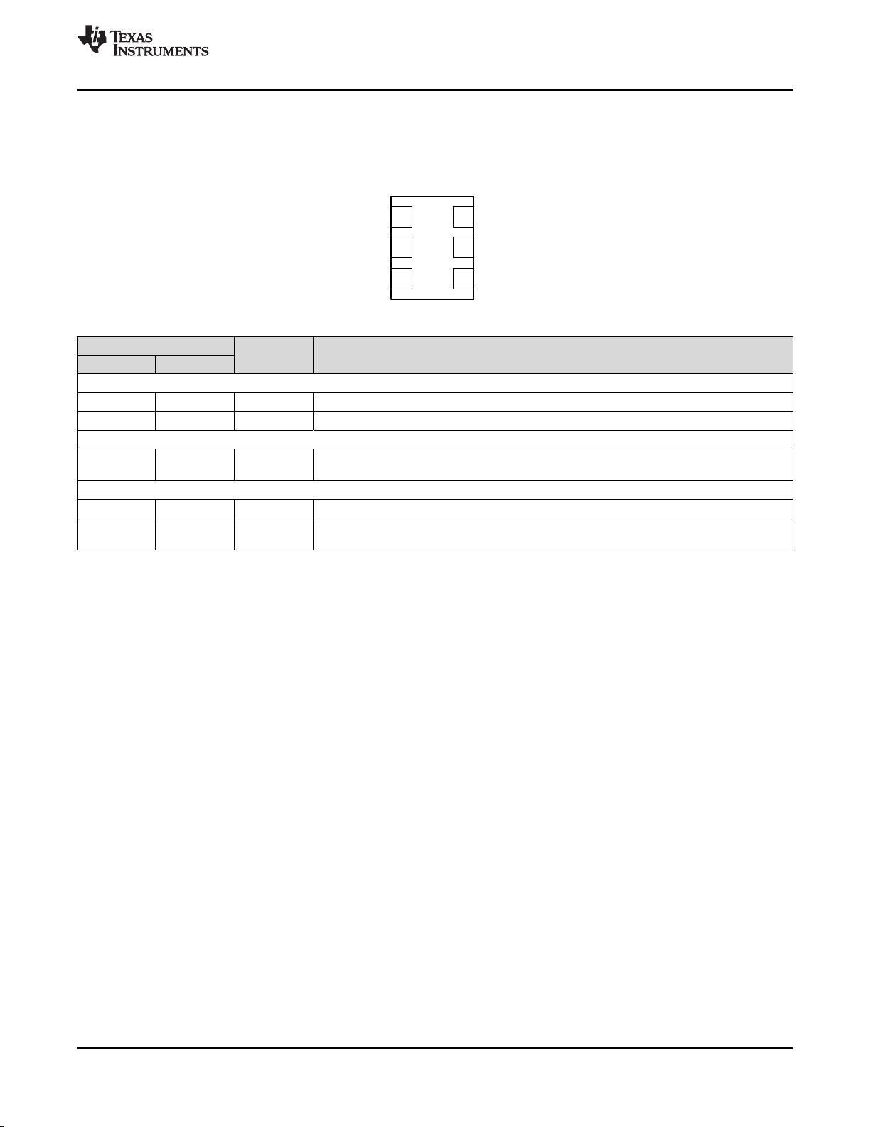
5 Pin Configuration and Functions......................... 3
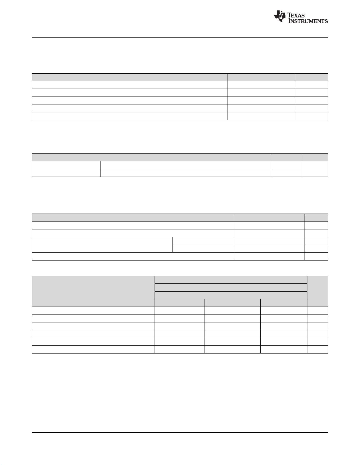
6 Specifications......................................................... 4
6.1 Absolute Maximum Ratings ...................................... 4
6.2 ESD Ratings ............................................................ 4
6.3 Recommended Operating Conditions....................... 4
6.4 Thermal Information.................................................. 4
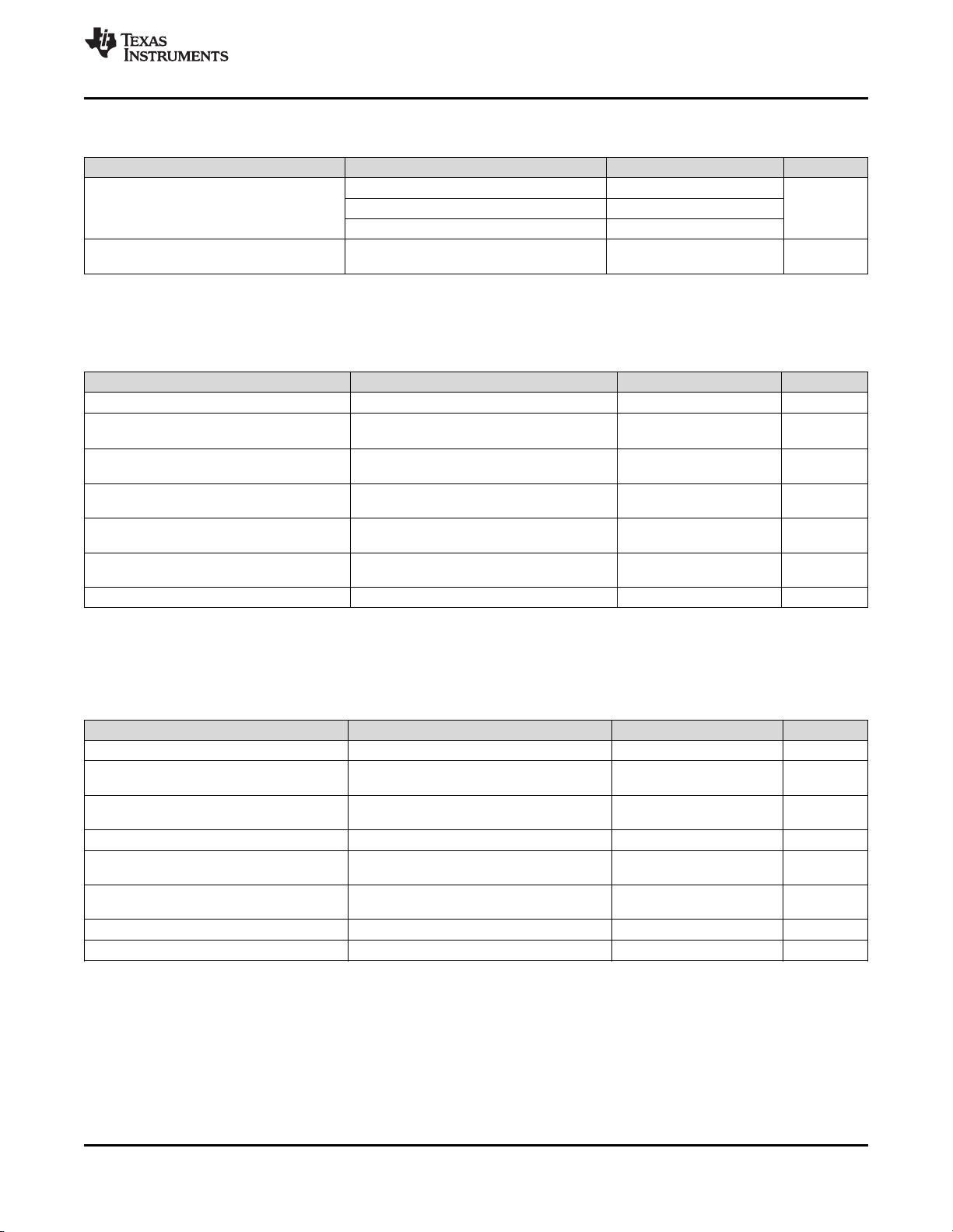
6.5 Electrical Characteristics - Power Supply ................. 5
6.6 LVPECL Output Characteristics................................ 5
6.7 LVDS Output Characteristics .................................... 5
6.8 HCSL Output Characteristics.................................... 6
6.9 OE Input Characteristics........................................... 6
6.10 Frequency Tolerance Characteristics ..................... 6
6.11 Power-On/Reset Characteristics (VDD).................. 6
6.12 PSRR Characteristics ............................................. 7
6.13 PLL Clock Output Jitter Characteristics .................. 7
6.14 Typical 156.25-MHz Output Phase Noise
Characteristics ........................................................... 7
6.15 Additional Reliability and Qualification.................... 7
6.16 Typical Characteristics............................................ 8
7 Parameter Measurement Information ................ 10
7.1 Device Output Configurations................................. 10
8 Power Supply Recommendations...................... 12
9 Layout ................................................................... 12
9.1 Layout Guidelines ................................................... 12
10 器器件件和和文文档档支支持持 ..................................................... 14
10.1 相关链接................................................................ 14
10.2 接收文档更新通知 ................................................. 14
10.3 社区资源................................................................ 14
10.4 商标 ....................................................................... 14
10.5 静电放电警告......................................................... 14
10.6 Glossary................................................................ 14
11 机机械械、、封封装装和和可可订订购购信信息息....................................... 15
4 修修订订历历史史记记录录
注:之前版本的页码可能与当前版本有所不同。
Changes from Revision C (September 2017) to Revision D Page
• 添加了 LMK61A2-644M ......................................................................................................................................................... 1
• 添加了 LMK61E0-156M.......................................................................................................................................................... 1
Changes from Revision B (March 2017) to Revision C Page
• 添加了 LMK61E0-155M.......................................................................................................................................................... 1
Changes from Revision A (November 2015) to Revision B Page
• 将数据表文本更新为最新的文档和转换标准 ........................................................................................................................... 1
• 添加了 LMK61E0-050M.......................................................................................................................................................... 1
• 更新了主要图形 ...................................................................................................................................................................... 1
• 添加了
接收文档更新通知
部分 .............................................................................................................................................. 14
Changes from Original (October 2015) to Revision A Page
• 将“产品预览”更改成了“生产数据数据表” ................................................................................................................................. 1
![](https://csdnimg.cn/release/download_crawler_static/87222257/bg3.jpg)
NC
OE
GND
1
2
3 4
5
6
OUTN
VDD
OUTP
3
LMK61E0-050M
,
LMK61E0-155M
,
LMK61E0-156M
,
LMK61E2-100M
,
LMK61E2-125M
LMK61E2-156M
,
LMK61E2-312M
,
LMK61A2-100M
,
LMK61A2-125M
,
LMK61A2-156M
LMK61A2-312M
,
LMK61A2-644M
,
LMK61I2-100M
www.ti.com.cn
ZHCSG14D –OCTOBER 2015–REVISED OCTOBER 2017
Copyright © 2015–2017, Texas Instruments Incorporated
5 Pin Configuration and Functions
SIA Package
6-Pin QFM
Top View
Pin Functions
PIN
I/O DESCRIPTION
NAME NO.
POWER
GND 3 Ground Device Ground.
VDD 6 Analog 3.3 V Power Supply.
OUTPUT BLOCK
OUTP,
OUTN
4, 5 Universal Differential Output Pair (LVPECL, LVDS or HCSL).
DIGITAL CONTROL / INTERFACES
NC 2 N/A No Connect.
OE 1 LVCMOS
Output Enable (internal pullup). When set to low, output pair is disabled and set at high
impedance.
![](https://csdnimg.cn/release/download_crawler_static/87222257/bg4.jpg)
4
LMK61E0-050M
,
LMK61E0-155M
,
LMK61E0-156M
,
LMK61E2-100M
,
LMK61E2-125M
LMK61E2-156M
,
LMK61E2-312M
,
LMK61A2-100M
,
LMK61A2-125M
,
LMK61A2-156M
LMK61A2-312M
,
LMK61A2-644M
,
LMK61I2-100M
ZHCSG14D –OCTOBER 2015–REVISED OCTOBER 2017
www.ti.com.cn
Copyright © 2015–2017, Texas Instruments Incorporated
(1) Stresses beyond those listed under Absolute Maximum Ratings may cause permanent damage to the device. These are stress ratings
only, which do not imply functional operation of the device at these or any other conditions beyond those indicated under Recommended
Operating Conditions. Exposure to absolute maximum-rated conditions for extended periods may affect device reliability.
6 Specifications
6.1 Absolute Maximum Ratings
over operating free-air temperature range (unless otherwise noted)
(1)
MIN MAX UNIT
VDD Device supply voltage –0.3 3.6 V
V
IN
Output voltage for logic inputs –0.3 VDD + 0.3 V
V
OUT
Output voltage for clock outputs –0.3 VDD + 0.3 V
T
J
Junction temperature 150 °C
T
STG
Storage temperature –40 125 °C
(1) JEDEC document JEP155 states that 500 V HBM allows safe manufacturing with a standard ESD control process.
(2) JEDEC document JEP157 states that 250 V CDM allows safe manufacturing with a standard ESD control process.
6.2 ESD Ratings
VALUE UNIT
V
(ESD)
Electrostatic
discharge
Human-body model (HBM), per ANSI/ESDA/JEDEC JS-001
(1)
±4000
V
Charged-device model (CDM), per JEDEC specification JESD22-C101
(2)
±1500
6.3 Recommended Operating Conditions
over operating free-air temperature range (unless otherwise noted)
MIN NOM MAX UNIT
VDD Device supply voltage 3.135 3.3 3.465 V
T
A
Ambient temperature –40 25 85 °C
T
J
Junction temperature
LMK61X2 125 °C
LMK61X0 115 °C
t
RAMP
VDD power-up ramp time 0.1 100 ms
(1) For more information about traditional and new thermal metrics, see the Semiconductor and IC Package Thermal Metrics application
report.
(2) The package thermal resistance is calculated on a 4 layer JEDEC board.
(3) Connected to GND with 3 thermal vias (0.3-mm diameter).
(4) ψJB (junction to board) is used when the main heat flow is from the junction to the GND pad. Please refer to Thermal Considerations
section for more information on ensuring good system reliability and quality.
6.4 Thermal Information
THERMAL METRIC
(1)
LMK61XX
(2) (3) (4)
UNIT
SIA (QFM)
6 PINS
Airflow (LFM) 0 Airflow (LFM) 200 Airflow (LFM) 400
R
θJA
Junction-to-ambient thermal resistance 55.2 46.4 43.7 °C/W
R
θJC(top)
Junction-to-case (top) thermal resistance 34.6 n/a n/a °C/W
R
θJB
Junction-to-board thermal resistance 37.7 n/a n/a °C/W
ψ
JT
Junction-to-top characterization parameter 11.3 17.6 22.5 °C/W
ψ
JB
Junction-to-board characterization parameter 37.7 41.5 40.1 °C/W
R
θJC(bot)
Junction-to-case (bottom) thermal resistance n/a n/a n/a °C/W
![](https://csdnimg.cn/release/download_crawler_static/87222257/bg5.jpg)
5
LMK61E0-050M
,
LMK61E0-155M
,
LMK61E0-156M
,
LMK61E2-100M
,
LMK61E2-125M
LMK61E2-156M
,
LMK61E2-312M
,
LMK61A2-100M
,
LMK61A2-125M
,
LMK61A2-156M
LMK61A2-312M
,
LMK61A2-644M
,
LMK61I2-100M
www.ti.com.cn
ZHCSG14D –OCTOBER 2015–REVISED OCTOBER 2017
Copyright © 2015–2017, Texas Instruments Incorporated
(1) Refer to Parameter Measurement Information for relevant test conditions.
(2) On-chip power dissipation should exclude 40 mW, dissipated in the 150 ohm termination resistors, from total power dissipation.
6.5 Electrical Characteristics - Power Supply
(1)
VDD = 3.3 V ± 5%, T
A
= -40C to 85°C
PARAMETER TEST CONDITIONS MIN TYP MAX UNIT
IDD Device current consumption LVPECL
(2)
162 208 mA
LVDS 152 196
HCSL 155 196
IDD-PD Device current consumption
when output is disabled
OE = GND 136 mA
(1) Refer to Parameter Measurement Information for relevant test conditions.
(2) An output frequency over f
OUT
max spec is possible, but output swing may be less than V
OD
min spec.
(3) Ensured by characterization.
6.6 LVPECL Output Characteristics
(1)
VDD = 3.3 V ± 5%, T
A
= -40C to 85°C
PARAMETER TEST CONDITIONS MIN TYP MAX UNIT
f
OUT
Output frequency
(2)
10 1000 MHz
V
OD
Output voltage swing
(V
OH
– V
OL
)
(2)
700 800 1200 mV
V
OUT, DIFF, PP
Differential output peak-to-
peak swing
2 ×
|V
OD
|
V
V
OS
Output common-mode voltage VDD –
1.55
V
t
R
/ t
F
Output rise/fall time (20% to
80%)
(3)
120 200 ps
PN-Floor Output phase noise floor
(f
OFFSET
> 10 MHz)
156.25 MHz –165 dBc/Hz
ODC Output duty cycle
(3)
45% 55%
(1) An output frequency over f
OUT
max spec is possible, but output swing may be less than V
OD
min spec.
(2) Ensured by characterization.
6.7 LVDS Output Characteristics
(1)
VDD = 3.3 V ± 5%, T
A
= –40°C to 85° C
PARAMETER TEST CONDITIONS MIN TYP MAX UNIT
f
OUT
Output frequency
(1)
10 900 MHz
V
OD
Output voltage swing
(V
OH
– V
OL
)
(1)
300 390 480 mV
V
OUT, DIFF, PP
Differential output peak-to-
peak swing
2 ×
|V
OD
|
V
V
OS
Output common-mode voltage 1.2 V
t
R
/ t
F
Output rise/fall time (20% to
80%)
(2)
150 250 ps
PN-Floor Output phase noise floor
(f
OFFSET
> 10 MHz)
156.25 MHz –162 dBc/Hz
ODC Output duty cycle
(2)
45% 55%
R
OUT
Differential output impedance 125 Ohm
剩余21页未读,继续阅读
资源评论
![avatar-default](https://csdnimg.cn/release/downloadcmsfe/public/img/lazyLogo2.1882d7f4.png)
![avatar](https://profile-avatar.csdnimg.cn/107303f5121d47e49d12d0a9ae68af10_weixin_54787054.jpg!1)
不觉明了
- 粉丝: 3231
- 资源: 5614
上传资源 快速赚钱
我的内容管理 展开
我的资源 快来上传第一个资源
我的收益
登录查看自己的收益我的积分 登录查看自己的积分
我的C币 登录后查看C币余额
我的收藏
我的下载
下载帮助
![voice](https://csdnimg.cn/release/downloadcmsfe/public/img/voice.245cc511.png)
![center-task](https://csdnimg.cn/release/downloadcmsfe/public/img/center-task.c2eda91a.png)
安全验证
文档复制为VIP权益,开通VIP直接复制
![dialog-icon](https://csdnimg.cn/release/downloadcmsfe/public/img/green-success.6a4acb44.png)