没有合适的资源?快使用搜索试试~ 我知道了~
TI-LMP7312.pdf
需积分: 9 0 下载量 19 浏览量
2022-12-04
20:46:03
上传
评论 4
收藏 1.76MB PDF 举报
温馨提示
试读
31页
TI-LMP7312.pdf
资源推荐
资源详情
资源评论
LMP7312
www.ti.com
SNOSB32B –MARCH 2010–REVISED MARCH 2013
LMP7312 Precision SPI-Programmable AFE with Differential/Single-Ended Input/Output
Check for Samples: LMP7312
1
FEATURES
DESCRIPTION
The LMP7312 is a digitally programmable variable
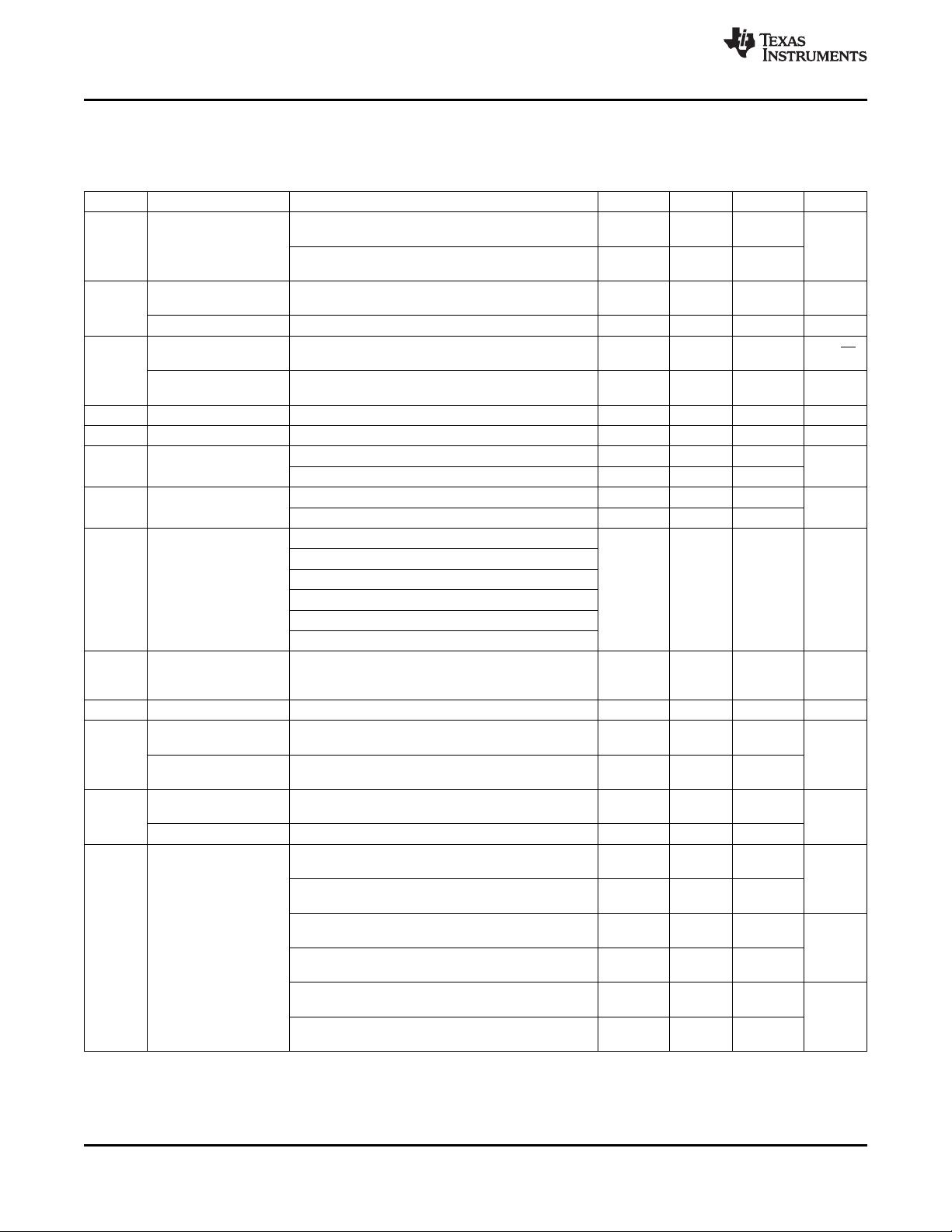
2
• Typical Values, T
A
= 25°C, V
+
=5V, V
-
=0V.
gain amplifier/attenuator. Its wide input voltage range
• Gain Bandwidth 1 MHz
and superior precision make it a prime choice for
• Input Voltage Range (G= 0.096 V/V) -15V to
applications requiring high accuracy such as data
+15V
acquisition systems for IO modules in programmable
logic control (PLC). The LMP7312 provides a
• Core Op-Amp Input Offset Voltage 100 µV
differential output to maximize dynamic range and
(Max)
signal to noise ratio, thereby reducing the overall
• Supply Current 2 mA (Max)
system error. It can also be configured to handle
• Gain (Attenuation Mode) 0.096 V/V, 0.192
single ended input data converters by means of the
V
OCM
pin (see Application Section for details). The
V/V0.384 V/V, 0.768 V/V
inputs of LMP7312 can be configured in attenuation
• Gain (Amplification Mode) 1 V/V, 2 V/V
mode to handle large input signals of up to +/- 15V,
• Gain Error 0.035% (Max)
as well as in amplification mode to handle current
• Core Op-Amp PSRR 90 dB (Min) loops of 0-20mA and 4-20mA.The LMP7312 is
equipped with a null switch to evaluate the offset of
• CMRR 80 dB (min)
the internal amplifier. A ensured 0.035% maximum
• Adjustable Output Common Mode 1V to 4V
gain error (for all gains) and a maximum gain drift of
• Temperature Range −40 to 125°C
5ppm over the extended industrial temperature range
(-40° to 125°C) make the LMP7312 very attractive for
• Package 14-Pin SOIC
high precision systems even under harsh conditions.
A low input offset voltage of 100µV and low voltage
APPLICATIONS
noise of 3µVpp give the LMP7312 a superior
• Signal Conditioning AFE
performance. The LMP7312 is fully specified from -
40° to 125°C and is available in SOIC-14 package.
– ±10V; ±5V; 0-5V; 0-10V; 0-20mA; 4-20mA
• Data Acquisition Systems
• Motor Control
• Instrument and Process Control
• Remote Sensing
• Programmable Automation Control
1
Please be aware that an important notice concerning availability, standard warranty, and use in critical applications of
Texas Instruments semiconductor products and disclaimers thereto appears at the end of this data sheet.
2All trademarks are the property of their respective owners.
PRODUCTION DATA information is current as of publication date.
Copyright © 2010–2013, Texas Instruments Incorporated
Products conform to specifications per the terms of the Texas
Instruments standard warranty. Production processing does not
necessarily include testing of all parameters.
SCK
CS
SDI
SDO
-
+
V
IO
-V
IN
+IN
+V
IN
V
OCM
SPI
Controller
R
F
P
+V
OUT
-V
OUT
/V
R
100 k:
100 k:
V
+
V
-
V
-
V
+
ADC
V
REF
V
+
ADC
V
CM
R
2
P
R
2
N
-IN
R
1
N
R
1
P
-+
I
S
4-20 mA
Driver
R
S
Sensor
-
+
R
F
N
LMP7312
SNOSB32B –MARCH 2010–REVISED MARCH 2013
www.ti.com
Typical Application
LMP™ is a trademark of Texas Instruments Corporation.
2 Submit Documentation Feedback Copyright © 2010–2013, Texas Instruments Incorporated
Product Folder Links: LMP7312
LMP7312
www.ti.com
SNOSB32B –MARCH 2010–REVISED MARCH 2013
These devices have limited built-in ESD protection. The leads should be shorted together or the device placed in conductive foam
during storage or handling to prevent electrostatic damage to the MOS gates.
Absolute Maximum Ratings
(1)(2)
ESD Rating
(3)
Human Body Model 2000V
Machine Body Model 150V
Charge device Model 1000V
Analog Supply Voltage (V
S
= V
+
- V
-
) 6V
DigitaI Supply Voltage (V
DIO
=V
IO
-V
-
) 6V
Attenuation pins -V
IN
, +V
IN
referred to V
-
±17.5V
Amplification pins -IN, +IN referred to V
-
±10V
Voltage at all other pins referred to V
-
6V
Storage Temperature Range -65°C to 150°C
For soldering specification: http://www.ti.com/lit/SNOA549
Junction Temperature 150°C
(1) Absolute Maximum Ratings indicate limits beyond which damage to the device may occur. Operating Ratings indicate conditions for
which the device is intended to be functional, but for which specific performance is not ensured. For ensured specifications and the test
conditions, see Electrical Characteristics.
(2) If Military/Aerospace specified devices are required, please contact the Texas Instruments Sales Office/ Distributors for availability and
specifications.
(3) Human Body Model, applicable std. MIL-STD-883, Method 3015.7. Machine Model, applicable std. JESD22–A115–A (ESD MM std. of
JEDEC). Field-Induced Charge-Device Model, applicable std. JESD22–C101–C (ESD FICDM std. of JEDEC).
Operating Ratings
(1)
Analog Supply Voltage (V
S
= V
+
– V
-
), V
-
=0V 4.5V to 5.5V
Digital Supply Voltage (V
DIO
= V
IO
– V
-
), V
-
=0V 2.7V to 5.5V
Attenuation pins -V
IN
, +V
IN
referred to V
-
-15V to 15V
Amplification pins -IN, +IN referred to V
-
-2.35V to 7.35V
Temperature Range
(2)
−40°C to 125°C
Package Thermal Resistance
(2)
SOIC-14 145°C/W
(1) Absolute Maximum Ratings indicate limits beyond which damage to the device may occur. Operating Ratings indicate conditions for
which the device is intended to be functional, but for which specific performance is not ensured. For ensured specifications and the test
conditions, see Electrical Characteristics.
(2) The maximum power dissipation is a function of TJ(max), θJA. The maximum allowable power dissipation at any ambient temperature
is: PD(max) = (TJ(max) – TA)/ θJA. All numbers apply for packages soldered directly onto a PC Board.
5V Electrical Characteristics
(1)
Unless otherwise specified, all limits ensured for T
A
= 25°C, V
+
= 5V, V
IO
= 5V, V
−
= 0V, G = 0.192 V/V, V
CM_ATT
=(+V
IN
+(-
V
IN
))/2, V
CM_AMP
=(+IN+(-IN))/2. Differential output configuration. SE = Single Ended Output, DE = Differential Output.Boldface
limits apply at the temperature extremes.
Symbol Parameter Conditions Min
(2)
Typ
(3)
Max
(2)
Units
V
OS
Core op-amp Input Nulling Switch Mode, DE, V
OCM
= 1V; –100 100
Offset Voltage Nulling switch Mode, SE, -V
OUT
/V
R
= 1V –250 250
µV
Nulling Switch Mode, DE, V
OCM
= 4V; –100 100
Nulling Switch Mode, SE, -V
OUT
/V
R
= 4V –250 250
(1) Electrical Table values apply only for factory testing conditions at the temperature indicated. Factory testing conditions result in very
limited self-heating of the device such that T
J
= T
A
. No ensured specification of parametric performance is indicated in the electrical
tables under conditions of internal self-heating where T
J
> T
A
.
(2) All limits are specified by testing, design, or statistical analysis.
(3) Typical values represent the most likely parametric norm at the time of characterization. Actual typical values may vary over time and
will also depend on the application and configuration. The typical values are not tested and are not ensured on shipped production
material.
Copyright © 2010–2013, Texas Instruments Incorporated Submit Documentation Feedback 3
Product Folder Links: LMP7312
LMP7312
SNOSB32B –MARCH 2010–REVISED MARCH 2013
www.ti.com
5V Electrical Characteristics
(1)
(continued)
Unless otherwise specified, all limits ensured for T
A
= 25°C, V
+
= 5V, V
IO
= 5V, V
−
= 0V, G = 0.192 V/V, V
CM_ATT
=(+V
IN
+(-
V
IN
))/2, V
CM_AMP
=(+IN+(-IN))/2. Differential output configuration. SE = Single Ended Output, DE = Differential Output.Boldface
limits apply at the temperature extremes.
Symbol Parameter Conditions Min
(2)
Typ
(3)
Max
(2)
Units
TCV
OS
Core op-amp Input Nulling Switch Mode, DE, V
OCM
= 1V; -3 ±1.5 3
Offset Voltage
(4)
Nulling Switch Mode, SE, -V
OUT
/V
R
= 1V
µV/°C
Nulling Switch Mode, DE, V
OCM
= 4V; -3 ±1.5 3
Nulling Switch Mode, SE, -V
OUT
/V
R
= 4V
All gains, R
L
= 10 kΩ, C
L
= 50pF, SE / DE –0.035 0.035
Gain Error %
–0.045 0.045
Av
Gain Drift SE / DE -5 ±1 5 ppm/°C
e
n
Core op-amp Voltage RTI, Nulling Switch Mode, f = 10 kHz 7.25
nV/√Hz
Noise Density
Core op-amp Peak to RTI, Nulling Switch Mode, f= 0.1Hz to 10Hz 3
µV
PP
Peak Voltage Noise
I
VA
Analog Supply Current +V
IN
= −V
IN
= V
OCM
2 mA
I
VIO
Digital Supply Current Without any load connected to SDO pin 120 μA
R
IN_CM
CM Input Resistance G= 0.192 V/V 62.08 kΩ
G= 1 V/V 40
R
IN_DIFF
Differential Input G= 0.192 V/V 248.3 kΩ
Resistance
G= 1 V/V 160
G= 0.096V/V, -15V < V
CM_ATT
< 15V, SE / DE
G= 0.192V/V, -11.4V < V
CM_ATT
< 15V, SE / DE
G= 0.384V/V, -6V < V
CM_ATT
< 11V, SE / DE
DC Common Mode 80
CMRR dB
Rejection Ratio 77
G= 0.768V/V, -3V < V
CM_ATT
< 8V, SE / DE
G= 1V/V, -2.3V < V
CM_AMP
< 7.3V, SE / DE
G= 2V/V, -1.15V < V
CM_AMP
< 6.15V, SE / DE.
PSRR Core op-amp DC Nulling Switch Mode, 4.5V <V
+
<5.5V 90 dB
Power Supply Rejection
Ratio
V
OCM_OS
V
OCM
Output Offset
(5)
V
OCM
= 2.5 V -20 20 mV
V
OUT
Positive Output Voltage R
L
= 10 kΩ, C
L
= 50 pF, V
+
−0.2
Swing +V
IN
= 15V, -V
IN
= -15V
V
Negative Output R
L
= 10 kΩ, C
L
= 50 pF, V
−
+0.2
Voltage Swing +V
IN
= -15V, -V
IN
= 15V
+V
IN
= -V
IN
= 2.5V, +V
OUT
, -V
OUT
/V
R
connected 10
Short circuit current
individually to either V
+
or V
-
I
OUT
mA
Current limitation Internal current limiter 55
Attenuation Mode, G = 0.096 V/V, R
L
=10 kΩ, 1.2
C
L
= 50 pF
MHz
Attenuation Mode, G = 0.192 V/V, R
L
= 10 kΩ, 1.0
C
L
= 50 pF
Attenuation Mode, G = 0.384 V/V, R
L
= 10 kΩ, 560
C
L
= 50 pF
GBW Bandwidth kHz
Attenuation Mode, G = 0.768 V/V, R
L
= 10 kΩ, 310
C
L
= 50 pF
Amplification Mode, G = 1 V/V, R
L
= 10 kΩ, 530
C
L
= 50 pF
kHz
Amplification Mode, G = 2 V/V, R
L
= 10 kΩ, 280
C
L
= 50 pF
(4) Offset voltage temperature drift is determined by dividing the change in V
OS
at the temperature extremes by the total temperature
change.
(5) V
OCM_OS
is the difference between the Output Common mode voltage (+V
OUT
+(-V
OUT
/V
R
))/2 and the Voltage on the V
OCM
pin.
4 Submit Documentation Feedback Copyright © 2010–2013, Texas Instruments Incorporated
Product Folder Links: LMP7312
LMP7312
www.ti.com
SNOSB32B –MARCH 2010–REVISED MARCH 2013
5V Electrical Characteristics
(1)
(continued)
Unless otherwise specified, all limits ensured for T
A
= 25°C, V
+
= 5V, V
IO
= 5V, V
−
= 0V, G = 0.192 V/V, V
CM_ATT
=(+V
IN
+(-
V
IN
))/2, V
CM_AMP
=(+IN+(-IN))/2. Differential output configuration. SE = Single Ended Output, DE = Differential Output.Boldface
limits apply at the temperature extremes.
Symbol Parameter Conditions Min
(2)
Typ
(3)
Max
(2)
Units
SR Slew Rate R
L
= 10 kΩ, C
L
= 50 pF 1.4
V/μsec
(6)
THD+N Total Harmonic Vout = 4.096 Vpp, f = 1KHz, 0.0026
%
Distorsion + Noise R
L
= 10 kΩ
(6) The number specified is the average of rising and falling slew rates and is measured at 90% to 10%.
Copyright © 2010–2013, Texas Instruments Incorporated Submit Documentation Feedback 5
Product Folder Links: LMP7312
剩余30页未读,继续阅读
资源评论
不觉明了
- 粉丝: 3163
- 资源: 5419
上传资源 快速赚钱
- 我的内容管理 展开
- 我的资源 快来上传第一个资源
- 我的收益 登录查看自己的收益
- 我的积分 登录查看自己的积分
- 我的C币 登录后查看C币余额
- 我的收藏
- 我的下载
- 下载帮助
最新资源
- [大模型部署]在C# Winform中使用文心一言ERNIE-3.5 4K 聊天模型
- python毕业设计-基于Django+OpenCV的二维码生成与识别系统设计与实现.zip
- python毕业设计-基于Django+OpenCV的二维码生成与识别系统设计与实现+使用说明.zip
- 基于STM32单片机空气监测系统设计源码+详细文档+配套全部资料(毕业设计).zip
- rdf0412-kcu116-pcie-c-2019-1.zip(XILINX KCU116 源码)
- 基于C#语言的winform界面火车票订票系统(源码+实验报告)
- 【华为OD部分真题及讲解】华为OD部分真题及讲解
- 基于Python+Django的京东商品比价系统源码+全部资料(毕业设计).zip
- G460 G560 Z460 Z560的最新BIOS 2.18版(无白名单)
- MetaJUI v0.4
资源上传下载、课程学习等过程中有任何疑问或建议,欢迎提出宝贵意见哦~我们会及时处理!
点击此处反馈
安全验证
文档复制为VIP权益,开通VIP直接复制
信息提交成功