TI-AMC1305M25-Q1.pdf
需积分: 5 93 浏览量
2022-11-27
16:22:12
上传
评论 4
收藏 2.04MB PDF 举报


DOUT
CLKIN
DVDD
DGND
AGND
AINP
AINN
AVDD
AMC1305-Q1
HV+
HV-
To Load
Floating
Power Supply
SD-Cx
SD-Dx
TMS320F2837x
3.3 V, or 5.0 V
R
SHUNT
Gate Driver
Gate Driver
5.0 V
Reinforced Isolation
PWMx
Copyright © 2016, Texas Instruments Incorporated
Product
Folder
Order
Now
Technical
Documents
Tools &
Software
Support &
Community
An IMPORTANT NOTICE at the end of this data sheet addresses availability, warranty, changes, use in safety-critical applications,
intellectual property matters and other important disclaimers. PRODUCTION DATA.
English Data Sheet: SBAS797
AMC1305L25-Q1
,
AMC1305M05-Q1
,
AMC1305M25-Q1
ZHCSFZ3 –FEBRUARY 2017
AMC1305x-Q1
高高精精度度、、增增强强隔隔离离式式 Δ-Σ 调调制制器器
1
1 特特性性
1
• 汽车电子 应用认证
• 具有符合 AEC-Q100 的下列结果:
– 温度等级 1:-40°C 至 +125°C
– 人体放电模式 (HBM) 静电放电 (ESD) 分类等级
2
– 组件充电模式 (CDM) ESD 分类等级 C6
• 与以下器件引脚兼容的系列:
– 输入电压范围为 ±50mV 或 ±250mV
– 互补金属氧化物半导体 (CMOS) 或低压差分信
令 (LVDS) 数字接口选项
• 出色的直流性能:
– 偏移误差:±50µV 或 ±150µV(最大值)
– 偏移漂移:1.3µV/°C(最大值)
– 增益误差:±0.3%(最大值)
– 增益漂移:±40ppm/°C(最大值)
• 安全相关认证:
– 7000 V
PK
增强型隔离,符合 DIN V VDE V
0884-10 (VDE V 0884-10): 2006-12 标准
– 符合 UL 1577 标准且长达 1 分钟的 5000 V
RMS
隔离
– CAN/CSA No. 5A 组件验收服务通知
• 瞬态抗扰度:15kV/µs(最小值)
• 高电磁场抗扰度
(请参见应用手册 SLLA181A)
• 5MHz 至 20MHz 外部时钟输入
2 应应用用
• 基于分流的电流感测或基于电阻分压器的电压感测
输入:
– 牵引逆变器
– 板载充电器 (OBC)
– 直流-直流转换器
– 电池管理系统 (BMS)
3 说说明明
AMC1305-Q1 器件是一款高精度 Δ-Σ (ΔΣ) 调制器,通
过磁场抗扰度较高的电容式双隔离栅隔离输出与输入电
路。根据 DIN V VDE V 0884-10、UL1577 和 CSA 标
准,该隔离栅经认证可提供高达 7000 V
峰值
的增强型
隔离。当与隔离电源配合使用时,该器件可防止共模高
电压线路上的噪声电流进入本地系统接地,从而干扰或
损害低电压电路。
AMC1305-Q1 针对直接连接分流电阻器或其它低电压
等级信号源进行了优化,同时具有出色的直流和交流性
能。分流电阻通常用于感测牵引逆变器、车载充电器或
类似汽车应用 中的电流。通过使用适当的数字滤波器
(即,集成于 TMS320F2837x)来抽取位流,该器件
可在 78kSPS 数据速率下实现 85dB (13.8 ENOB) 动
态范围的 16 位分辨率。
在高侧,调制器由 5V (AVDD) 标称电压供电,而隔离
数字接口则由 3.3V 或 5V 电源 (DVDD) 供电。
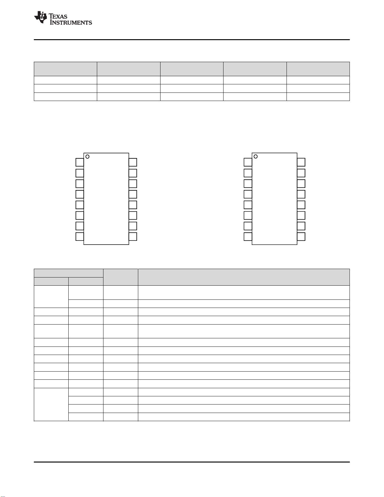
AMC1305-Q1 采用宽体小外形尺寸集成电路 (SOIC)-
16 (DW) 封装。
器器件件信信息息
(1)
器器件件型型号号 封封装装 封封装装尺尺寸寸((标标称称值值))
AMC1305x-Q1 SOIC (16) 10.30mm x 7.50mm
(1) 如需了解所有可用封装,请参见数据表末尾的可订购产品附
录。
简简化化电电路路原原理理图图


剩余42页未读,继续阅读
资源评论


