TI1-TMS465169.pdf
需积分: 0 142 浏览量
2022-12-10
23:04:23
上传
评论 4
收藏 470KB PDF 举报


SMHS566B − JUNE 1997 − REVISED APRIL 1998
1
POST OFFICE BOX 1443 • HOUSTON, TEXAS 77251−1443
D Organization ...4194304 by 16 Bits
D Single 3.3-V Power Supply (± 0.3 V
Tolerance)
D Performance Ranges:
ACCESS ACCESS ACCESS EDO
TIME TIME TIME CYCLE
t
RAC
t
CAC
t
AA
t
HPC
MAX MAX MAX MIN
’46x169/P-50 50 ns 13 ns 25 ns 20 ns
’46x169/P-60 60 ns 15 ns 30 ns 25 ns
D Extended-Data-Out (EDO) Operation
D xCAS-Before-RAS (xCBR) Refresh
D Long Refresh Period and Self-Refresh
Option (TMS46x169P)
D 3-State Unlatched Output
D Low Power Dissipation
D High-Reliability Plastic 50-Lead
400-Mil-Wide Surface-Mount Thin
Small-Outline Package (TSOP) (DGE Suffix)
D Operating Free-Air Temperature Range
0°C to 70°C
AVAILABLE OPTIONS
DEVICE
POWER
SUPPLY
SELF-
REFRESH,
BATTERY
BACKUP
REFRESH
CYCLES
TMS465169 3.3 V — 4096 in 64 ms
TMS465169P 3.3 V Yes 4096 in 128 ms
description
The and TMS465169 is a high-speed,
67108864-bit dynamic random-access memory
(DRAM) device organized as 4194304 words of
16 bits. The TMS465169P is similar DRAM but
includes a long refresh period and a self-refresh
option. Both employ state-of-the-art technology
for high performance, reliability, and low power at
low cost.
Please be aware that an important notice concerning availability, standard warranty, and use in critical applications o
f
Texas Instruments semiconductor products and disclaimers thereto appears at the end of this data sheet.
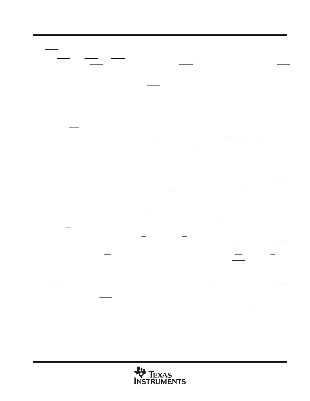
PIN NOMENCLATURE
A0−A12
†
Address Inputs
DQ0−DQ15 Data In/ Data Out
LCAS
Lower Column-Address Strobe
UCAS
Upper Column-Address Strobe
NC No Internal Connection
OE
Output Enable
RAS
Row-Address Strobe
V
CC
3.3-V Supply
V
SS
Ground
W
Write Enable
V
SS
DQ15
DQ14
DQ13
DQ12
V
SS
DQ11
DQ10
DQ9
DQ8
NC
V
SS
LCAS
UCAS
1
2
3
4
5
6
7
8
9
10
11
12
13
14
50
49
48
47
46
45
44
43
42
41
40
39
38
37
V
CC
DQ0
DQ1
DQ2
DQ3
V
CC
DQ4
DQ5
DQ6
DQ7
NC
V
CC
W
RAS
OE
NC
NC
A12/NC
†
A11
A10
A9
A8
A7
A6
V
SS
DGE PACKAGE
(TOP VIEW)
15
16
17
18
19
20
21
22
23
24
25
36
35
34
33
32
31
30
29
28
27
26
NC
NC
W
NC
A0
A1
A2
A3
A4
A5
V
CC
†
A12 is NC for TMS465169 and TMS465169P.
!" # $%&" !# '%()$!" *!"&+
*%$"# $ " #'&$$!"# '& ",& "&# &-!# #"%&"#
#"!*!* .!!"/+ *%$" '$&##0 *&# " &$&##!)/ $)%*&
"&#"0 !)) '!!&"&#+
Copyright 1998, Texas Instruments Incorporated


剩余29页未读,继续阅读


评论0
最新资源