TI-INA148-Q1.pdf
需积分: 9 102 浏览量
2022-11-24
23:32:35
上传
评论 5
收藏 1.08MB PDF 举报


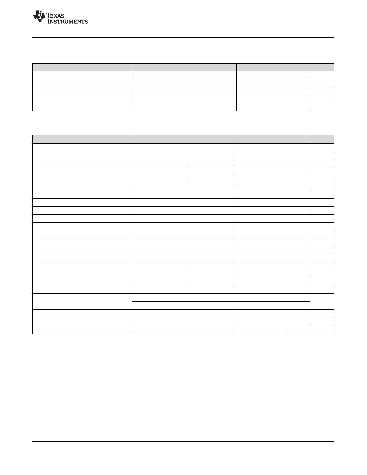
Output Voltage (V)
Common Mode Voltage (V)
-20 -15 -10 -5 0 5 10 15 20
-250
-200
-150
-100
-50
0
50
100
150
200
250
D001
Product
Folder
Sample &
Buy
Technical
Documents
Tools &
Software
Support &
Community
An IMPORTANT NOTICE at the end of this data sheet addresses availability, warranty, changes, use in safety-critical applications,
intellectual property matters and other important disclaimers. PRODUCTION DATA.
INA148-Q1
SBOS472B –MARCH 2009–REVISED JUNE 2016
INA148-Q1 ±200-V Common-Mode Voltage Difference Amplifier
1
1 Features
1
• Qualified for Automotive Applications
• AEC-Q100 Qualified With the Following Results:
– Device Temperature Grade 1: –40°C to 125°C
Ambient Operating Temperature Range
– Device HBM ESD Classification Level 1C
– Device CDM ESD Classification Level C6
– Device MM ESD Classification Level M2
• High Common-Mode Voltage
– 75 V at V
S
= 5 V
– ±200 V at V
S
= ±15 V
• Fixed Differential Gain = 1 V/V
• Low Quiescent Current: 260 µA
• Wide Supply Range
– Single Supply: 2.7 V to 36 V
– Dual Supplies: ±1.35 V to ±18 V
• Low Gain Error: 0.075% (Maximum)
• Low Nonlinearity: 0.002% (Maximum)
• High CMR: 86 dB
• Surface-Mount 8-pin SOIC Package
2 Applications
• HEV/EV and Powertrain
• HEV Battery Management
• Automotive Instrumentation
• Current-Shunt Measurements
• Differential Sensor Amplifiers
• Line Receivers
• Battery-Powered Systems
• Stacked-Cell Monitors
3 Description
The INA148-Q1 is a precision, low-power, unity-gain
difference amplifier with a high common-mode input
voltage range. The device consists of a monolithic,
precision, bipolar operational amplifier with a thin-film
resistor network.
The on-chip resistors are laser trimmed for an
accurate 1-V/V differential gain and high common-
mode rejection. Excellent temperature tracking of the
resistor network maintains high gain accuracy and
common-mode rejection over temperature. The
INA148-Q1 operates on single or dual supplies.
These features make the INA148-Q1 suitable for
HEV/EV and Powertrain applications, specifically in
battery management systems.
The INA148-Q1 is available in an 8-pin SOIC,
surface-mount package, and is specified for operation
over the temperature range of –40°C to 125°C.
Device Information
(1)
PART NUMBER PACKAGE BODY SIZE (NOM)
INA148-Q1 SOIC (8) 3.91 mm × 4.90 mm
(1) For all available packages, see the orderable addendum at
the end of the data sheet.
.
Input Common-Mode Voltage vs Output Voltage


剩余24页未读,继续阅读
资源评论


不觉明了
- 粉丝: 3203
- 资源: 5558


