TI-BQ2011.pdf
需积分: 10 102 浏览量
2022-10-29
20:56:22
上传
评论 5
收藏 813KB PDF 举报


Features
➤
Conservative and repeatable
measurement of available charge
in rechargeable batteries
➤
Designed for portable equipment
such as power tools with high dis
-
charge rates
➤
Designed for battery pack inte
-
gration
-
120µA typical standby current
(self-discharge estimation mode)
-
Small size enables imple-
mentations in as little as
1
2
square inch of PCB
➤ Direct drive of LEDs for capacity
display
➤ Self-discharge compensation us-
ing internal temperature sensor
➤ Simple single-wire serial commu-
nications port for subassembly
testing
➤
16-pin narrow SOIC
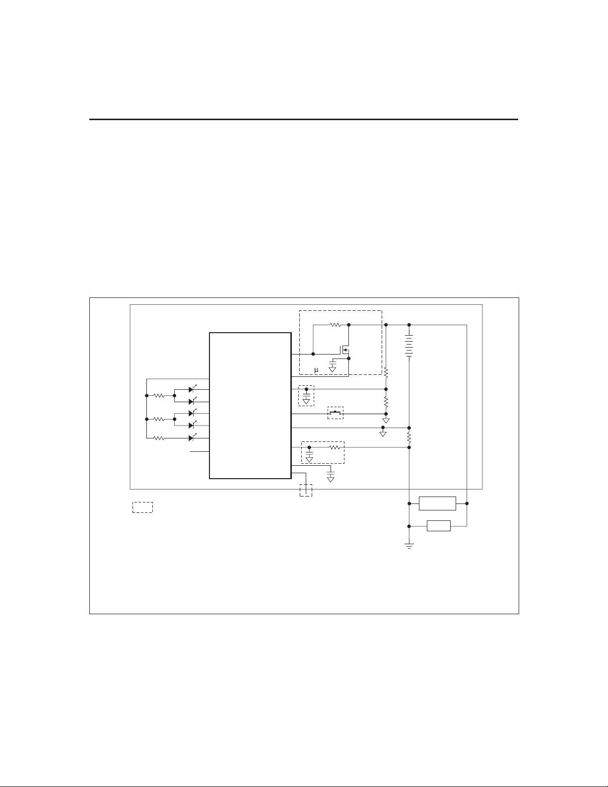
General Description
The bq2011 Gas Gauge IC is intended
for battery-pack installation to main
-
tain an accurate record of available
battery charge. The IC monitors a
voltage drop across a sense resistor
connected in series between the nega
-
tive battery terminal and ground to
determine charge and discharge ac
-
tivity of the battery. The bq2011 is
designed for systems such as power
tools with very high discharge rates.
Battery self-discharge is estimated
based on an internal timer and tem
-
perature sensor. Compensations for
battery temperature and rate of
charge or discharge are applied to
the charge, discharge, and
selfdischarge calculations to provide
available charge information across
a wide range of operating conditions.
Initial battery capacity is set using
the PFC and MODE pins. Actual
battery capacity is automatically
“learned” in the course of a dis-
charge cycle from full to empty and
may be displayed depending on the
display mode.
Nominal available charge may be di
-
rectly indicated using a five-seg
-
ment LED display. These segments
are used to indicate graphically the
nominal available charge.
The bq2011 supports a simple single-
line bidirectional serial link to an exter
-
nal processor (common ground). The
bq2011 outputs battery information in
response to external commands over the
serial link. To support subassembly
testing, the outputs may also be con
-
trolled by command. The external proc
-
essor may also overwrite some of the
bq2011 gas gauge data registers.
The bq2011 may operate directly
from four cells. With the REF output
and an external transistor, a simple,
inexpensive regulator can be built to
provide V
CC
from a greater number
of cells.
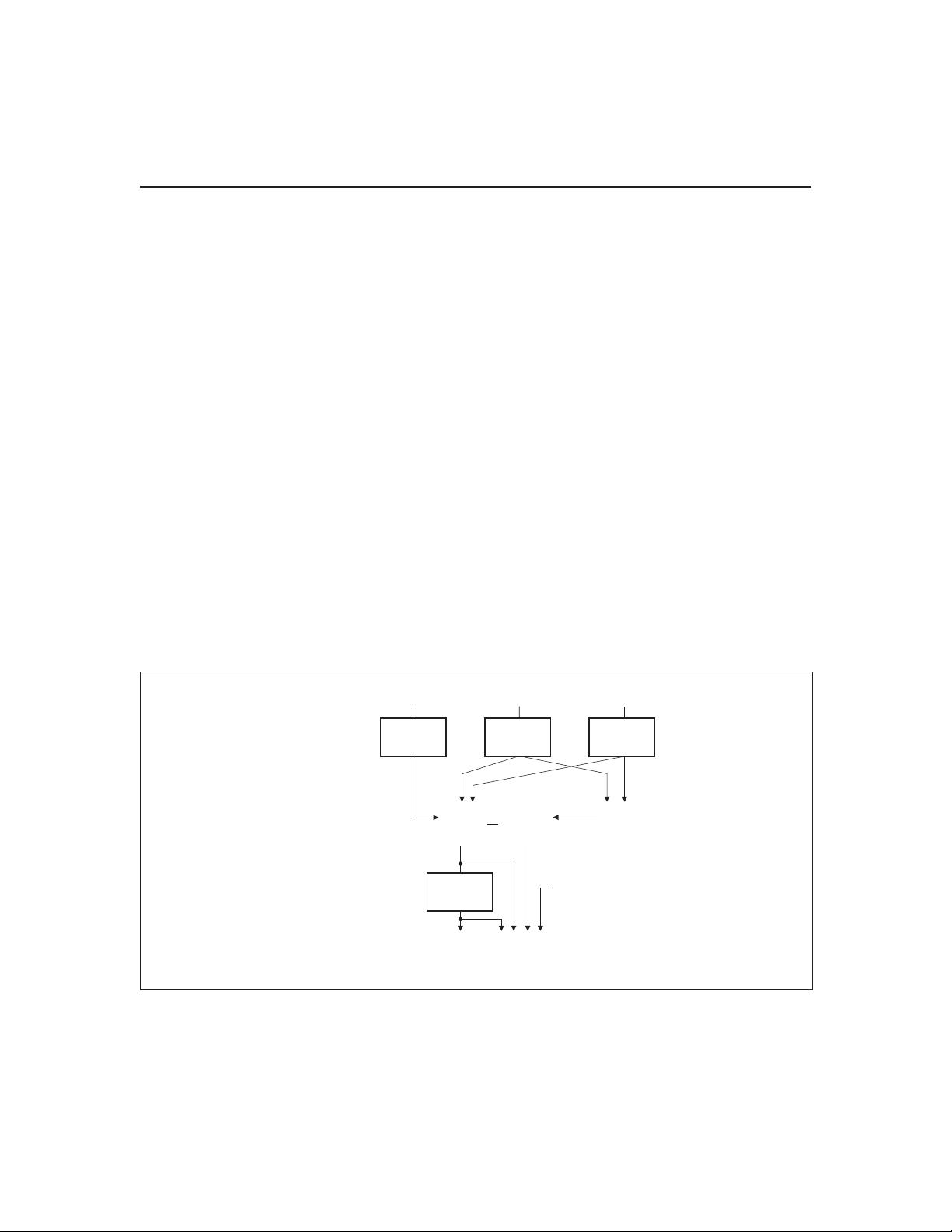
Internal registers include available
charge, temperature, capacity, battery
ID, and battery status.
1
Gas Gauge IC for
High Discharge Rates
2/96 E
Pin Connections Pin Names
1
PN201101.eps
16-Pin Narrow SOIC
2
3
4
5
6
7
8
16
15
14
13
12
11
10
9
V
CC
REF
NC
DQ
RBI
SB
DISP
SR
MODE
SEG
1
SEG
2
SEG
3
SEG
4
SEG
5
PFC
V
SS
MODE Display mode output
SEG
1
LED segment 1
SEG
2
LED segment 2
SEG
3
LED segment 3
SEG
4
LED segment 4
SEG
5
LED segment 5
PFC Programmed full count
selection input
REF Voltage reference output
NC No connect
DQ Serial communications
input/output
RBI Register backup input
SB Battery sense input
DISP
Display control input
SR Sense resistor input
V
CC
3.0–6.5V
V
SS
Negative battery terminal
bq2011


剩余24页未读,继续阅读
资源评论


不觉明了
- 粉丝: 3248
- 资源: 5614


最新资源
- 如何在C++中使用 vector 的引用语义
- 上市公司-环境绩效数据(EP)(2008-2022年)含dta数据
- QT中QSettings的使用系列之一:初步使用
- 最新版: PowerShell-7.4.3-win-x64.msi
- 小程序版python语言pytorch框架训练识别非机动车骑行有无佩戴安全帽-不含数据集图片-含逐行注释和说明文档.zip
- 上市公司-管理层治理能力(2000-2023年)数据合集,超全变量 权威详细
- 小程序版图像分类算法对墙体裂缝识别-不含数据集图片-含逐行注释和说明文档.zip
- QT中QSettings的使用系列之二:保存和恢复应用程序主窗口
- 小程序版深度学习CNN训练识别图片中是否含有行人-不含数据集图片-含逐行注释和说明文档.zip
- 小程序版python语言pytorch框架的图像分类玻璃是否破碎识别-不含数据集图片-含逐行注释和说明文档.zip
资源上传下载、课程学习等过程中有任何疑问或建议,欢迎提出宝贵意见哦~我们会及时处理!
点击此处反馈


