MAX1632EAI maxim 美信芯片 电子元器件中文版规格手册.pdf
需积分: 5 139 浏览量
2023-06-06
10:21:12
上传
评论
收藏 283KB PDF 举报


For pricing, delivery, and ordering information, please contact Maxim/Dallas Direct! at
1-888-629-4642, or visit Maxim’s website at www.maxim-ic.com.
________________General Description
The MAX1630–MAX1635 are buck-topology, step-down,
switch-mode, power-supply controllers that generate
logic-supply voltages in battery-powered systems. These
high-performance, dual/triple-output devices include on-
board power-up sequencing, power-good signaling with
delay, digital soft-start, secondary winding control, low-
dropout circuitry, internal frequency-compensation net-
works, and automatic bootstrapping.
Up to 96% efficiency is achieved through synchronous
rectification and Maxim’s proprietary Idle Mode™ control
scheme. Efficiency is greater than 80% over a 1000:1
load-current range, which extends battery life in system-
suspend or standby mode. Excellent dynamic response
corrects output load transients caused by the latest
dynamic-clock CPUs within five 300kHz clock cycles.
Strong 1A on-board gate drivers ensure fast external
N-channel MOSFET switching.
These devices feature a logic-controlled and synchroniz-
able, fixed-frequency, pulse-width-modulation (PWM)
operating mode. This reduces noise and RF interference
in sensitive mobile communications and pen-entry appli-
cations. Asserting the SKIP pin enables fixed-frequency
mode, for lowest noise under all load conditions.
The MAX1630–MAX1635 include two PWM regulators,
adjustable from 2.5V to 5.5V with fixed 5.0V and 3.3V
modes. All these devices include secondary feedback
regulation, and the MAX1630/MAX1632/MAX1633/
MAX1635 each contain 12V/120mA linear regulators. The
MAX1631/MAX1634 include a secondary feedback input
(SECFB), plus a control pin (STEER) that selects which
PWM (3.3V or 5V) receives the secondary feedback sig-
nal. SECFB provides a method for adjusting the sec-
ondary winding voltage regulation point with an external
resistor divider, and is intended to aid in creating auxiliary
voltages other than fixed 12V.
The MAX1630/MAX1631/MAX1632 contain internal out-
put overvoltage and undervoltage protection features.
________________________Applications
Notebook and Subnotebook Computers
PDAs and Mobile Communicators
Desktop CPU Local DC-DC Converters
____________________________Features
♦ 96% Efficiency
♦ +4.2V to +30V Input Range
♦ 2.5V to 5.5V Dual Adjustable Outputs
♦ Selectable 3.3V and 5V Fixed or Adjustable
Outputs (Dual Mode™)
♦ 12V Linear Regulator
♦ Adjustable Secondary Feedback
(MAX1631/MAX1634)
♦ 5V/50mA Linear Regulator Output
♦ Precision 2.5V Reference Output
♦ Programmable Power-Up Sequencing
♦ Power-Good (RESET) Output
♦ Output Overvoltage Protection
(MAX1630/MAX1631/MAX1632)
♦ Output Undervoltage Shutdown
(MAX1630/MAX1631/MAX1632)
♦ 200kHz/300kHz Low-Noise, Fixed-Frequency
Operation
♦ Low-Dropout, 99% Duty-Factor Operation
♦ 2.5mW Typical Quiescent Power (+12V input, both
SMPSs on)
♦ 4μA Typical Shutdown Current
♦ 28-Pin SSOP Package
MAX1630–MAX1635
Multi-Output, Low-Noise Power-Supply
Controllers for Notebook Computers
________________________________________________________________ Maxim Integrated Products 1
5V
LINEAR
12V
LINEAR
POWER-UP
SEQUENCE
POWER-
GOOD
3.3V
SMPS
5V
SMPS
RESETON/OFF
+5V (RTC)
+3.3V
INPUT
+5V
+12V
________________Functional Diagram
19-0480; Rev 4; 8/05
EVALUATION KIT
AVAILABLE
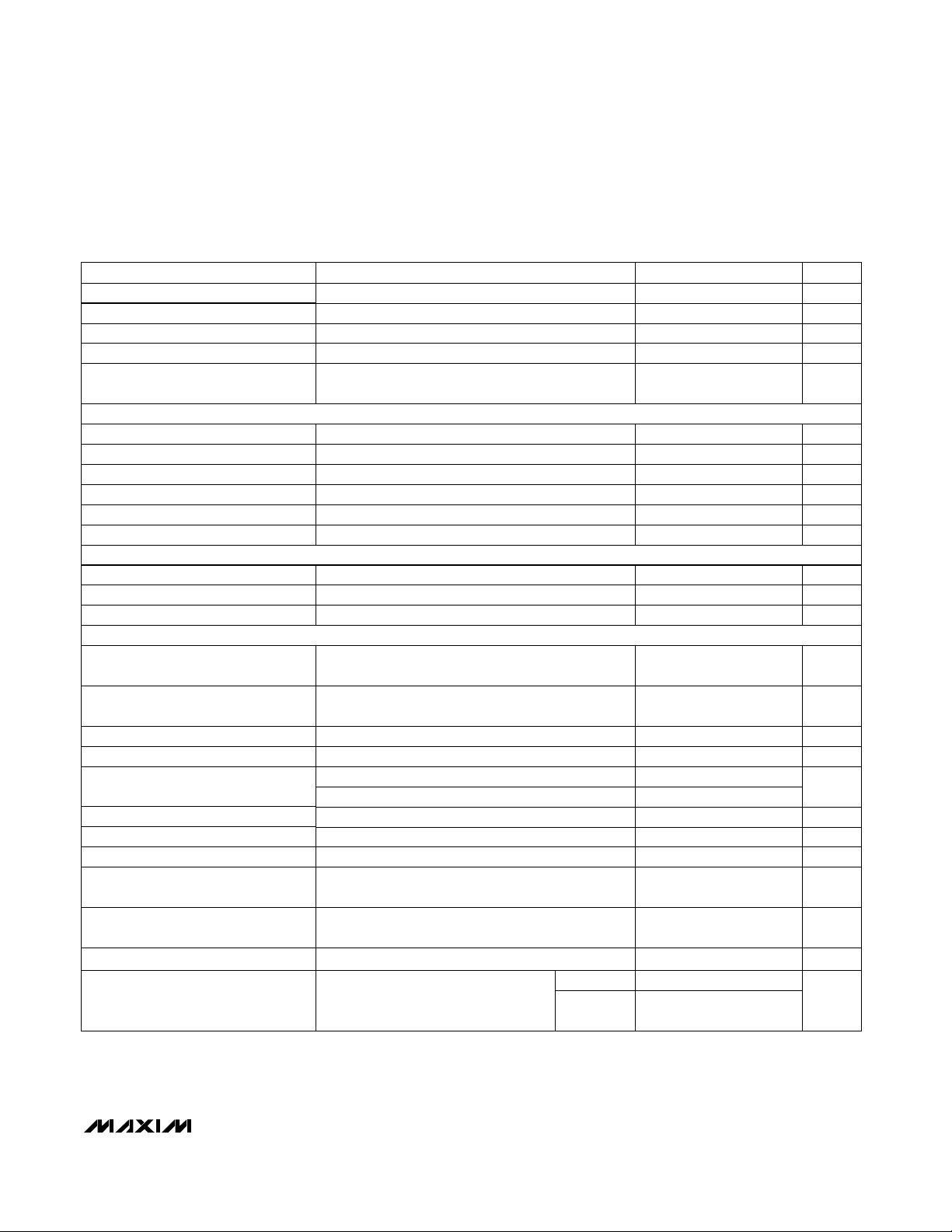
_______________Ordering Information
Ordering Information continued at end of data sheet.
Pin Configurations and Selector Guide appear at end of data
sheet.
Idle Mode and Dual Mode are trademarks of Maxim Integrated
Products.
+ Denotes lead-free package.
PART TEMP RANGE
PIN-PACKAGE
MAX1630CAI 0°C to +70°C 28 SSOP
MAX1630CAI+ 0°C to +70°C 28 SSOP
MAX1630EAI+ -40°C to +85°C 28 SSOP


剩余29页未读,继续阅读
资源评论


芯脉芯城
- 粉丝: 3
- 资源: 4031


最新资源
- Picasso_v3.1 2.ipa
- chromedriver-mac-arm64.zip
- 蓝zapro.apk
- chromedriver-linux64.zip
- UCAS研一深度学习实验-MNIST手写数字识别python源码+详细注释(高分项目)
- 基于Python和PyTorch框架完成的一个手写数字识别实验源码(带MINIST手写数字数据集)+详细注释(高分项目)
- 基于Matlab在MNIST数据集上利用CNN完成手写体数字识别任务,并实现单层CNN反向传播算法+源代码+文档说明(高分项目)
- NVIDIA驱动、CUDA和Pytorch及其依赖
- 基于SVM多特征融合的微表情识别python源码+项目说明+详细注释(高分课程设计)
- html动态爱心代码一(附源码)
资源上传下载、课程学习等过程中有任何疑问或建议,欢迎提出宝贵意见哦~我们会及时处理!
点击此处反馈


