没有合适的资源?快使用搜索试试~ 我知道了~
MAX1402EAI-T maxim 美信芯片 电子元器件中文版规格手册.pdf
需积分: 5 0 下载量 94 浏览量
2023-06-05
10:55:11
上传
评论
收藏 548KB PDF 举报
温馨提示
试读
39页
MAX1402EAI-T maxim 美信芯片 电子元器件中文版规格手册
资源推荐
资源详情
资源评论
General Description
The MAX1402 low-power, multichannel, serial-output
analog-to-digital converter (ADC) features matched
200µA current sources for sensor excitation. This ADC
uses a sigma-delta modulator with a digital decimation
filter to achieve 16-bit accuracy. The digital filter’s user-
selectable decimation factor allows the conversion res-
olution to be reduced in exchange for a higher output
data rate. True 16-bit performance is achieved at an
output data rate of up to 480sps. In addition, the modu-
lator sampling frequency may be optimized for either
lowest power dissipation or highest throughput rate.
The MAX1402 operates from a +5V supply.
This device offers three fully differential input channels
that may be independently programmed with a gain
between +1V/V and +128V/V. Furthermore, it can com-
pensate an input-referred DC offset up to 117% of the
selected full-scale range. These three differential chan-
nels may also be configured to operate as five pseudo-
differential input channels. Two additional, fully
differential system-calibration channels are provided for
gain and offset error correction.
The MAX1402 may be configured to sequentially scan all
signal inputs and provide the results via the serial inter-
face with minimum communications overhead. When
used with a 2.4576MHz or 1.024MHz master clock, the
digital decimation filter can be programmed to produce
zeros in its frequency response at the line frequency and
associated harmonics, ensuring excellent line rejection
without the need for further post-filtering.
The MAX1402 is available in a 28-pin SSOP package.
Applications
Portable Industrial Instruments
Portable Weigh Scales
Loop-Powered Systems
Pressure Transducers
Features
♦ 18-Bit Resolution, Sigma-Delta ADC
♦ 16-Bit Accuracy with No Missing Codes to 480sps
♦ Low Quiescent Current
250µA (operating mode)
2µA (power-down mode)
♦ Matched On-Board Current Sources (200µA) for
Sensor Excitation
♦ 3 Fully Differential or 5 Pseudo-Differential Signal
Input Channels
♦ 2 Additional, Fully Differential Calibration
Channels/Auxiliary Input Channels
♦ Programmable Gain and Offset
♦ Fully Differential Reference Inputs
♦ Converts Continuously or On Command
♦ Automatic Channel Scanning and Continuous
Data Output Mode
♦ Operates with +5V Analog Supply and +3V or +5V
Digital Supply
♦ 3-Wire Serial Interface—SPI™/QSPI™ Compatible
♦ 28-Pin SSOP Package
MAX1402
+5V, 18-Bit, Low-Power, Multichannel,
Oversampling (Sigma-Delta) ADC
________________________________________________________________ Maxim Integrated Products 1
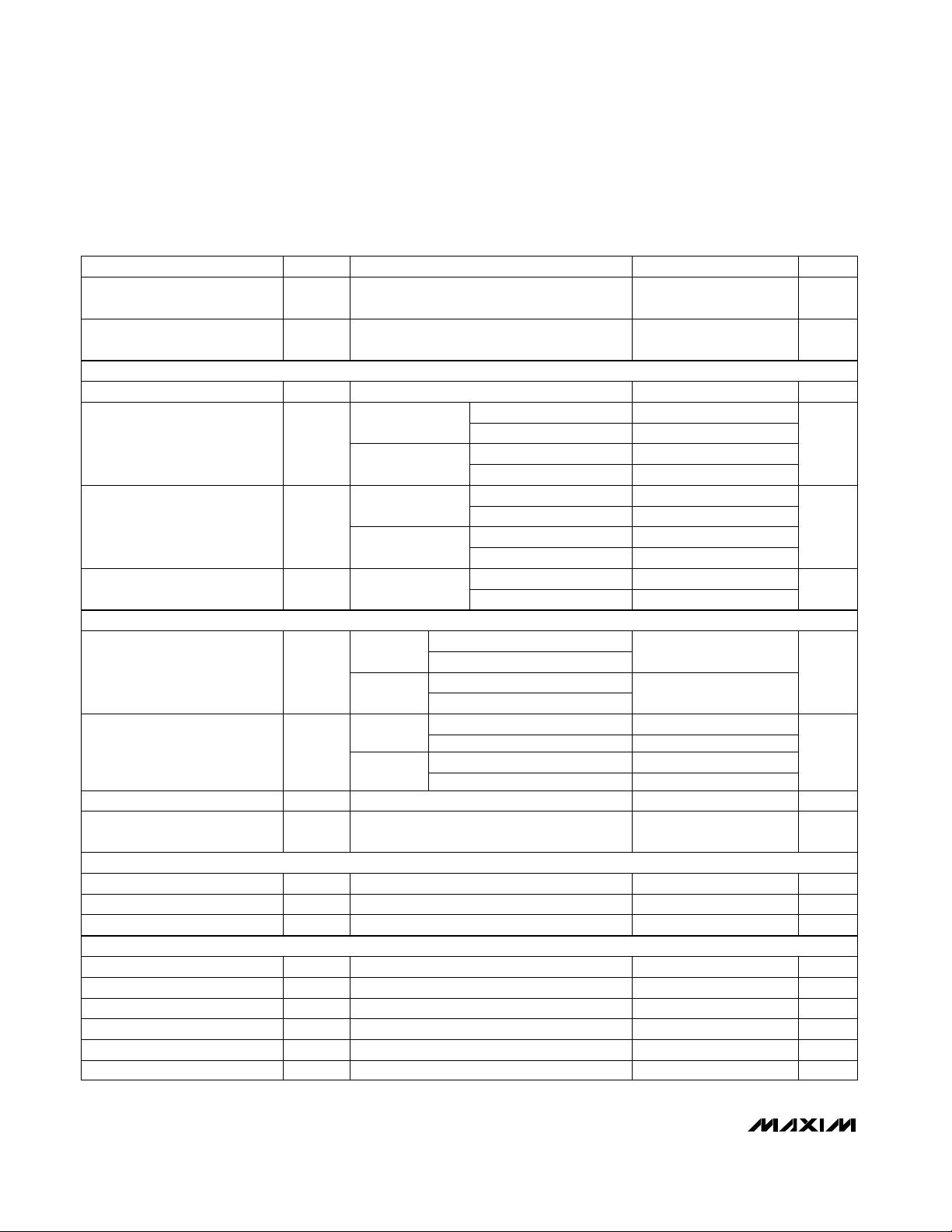
28
27
26
25
24
23
22
21
20
19
18
17
16
15
1
2
3
4
5
6
7
8
9
10
11
12
13
14
SCLK
DIN
DOUT
INT
V
DD
DGND
AIN5
CALOFF+
CALOFF-
REFIN+
REFIN-
CALGAIN+
CALGAIN-
AIN6
AIN4
AIN3
AIN2
AIN1
V+
AGND
OUT1
OUT2
MUXOUT-
MUXOUT+
RESET
CS
CLKOUT
CLKIN
SSOP
TOP VIEW
MAX1402
Pin Configuration
Ordering Information
SPI and QSPI are trademarks of Motorola, Inc.
19-1423; Rev 2; 1/07
For pricing, delivery, and ordering information, please contact Maxim/Dallas Direct! at
1-888-629-4642, or visit Maxim’s website at www.maxim-ic.com.
EVALUATION KIT
AVAILABLE
PART TEMP RANGE
PIN-
PACKAGE
PKG
CODE
MAX1402CAI
0°C to +70°C 28 SSOP A28-2
MAX1402EAI
-40°C to +85°C 28 SSOP A28-2
%FSR
MAX1402
+5V, 18-Bit, Low-Power, Multichannel,
Oversampling (Sigma-Delta) ADC
2 _______________________________________________________________________________________
ABSOLUTE MAXIMUM RATINGS
ELECTRICAL CHARACTERISTICS
(V+ = +5V ±5%, V
DD
= +2.7V to +5.25V, V
REFIN+
= +2.50V, REFIN- = AGND, f
CLKIN
= 2.4576MHz, T
A
= T
MIN
to T
MAX
, unless other-
wise noted. Typical values are at T
A
= +25°C.)
Stresses beyond those listed under “Absolute Maximum Ratings” may cause permanent damage to the device. These are stress ratings only, and functional
operation of the device at these or any other conditions beyond those indicated in the operational sections of the specifications is not implied. Exposure to
absolute maximum rating conditions for extended periods may affect device reliability.
V+ to AGND, DGND .................................................-0.3V to +6V
V
DD
to AGND, DGND...............................................-0.3V to +6V
AGND to DGND.....................................................-0.3V to +0.3V
Analog Inputs to AGND................................-0.3V to (V+ + 0.3V)
Analog Outputs to AGND .............................-0.3V to (V+ + 0.3V)
Reference Inputs to AGND...........................-0.3V to (V+ + 0.3V)
CLKIN and CLKOUT to DGND...................-0.3V to (V
DD
+ 0.3V)
All Other Digital Inputs to DGND..............................-0.3V to +6V
All Digital Outputs to DGND.......................-0.3V to (V
DD
+ 0.3V)
Maximum Current Input into Any Pin ..................................50mA
Continuous Power Dissipation (T
A
= +70°C)
28-Pin SSOP (derate 9.52mW/°C above +70°C) ........524mW
Operating Temperature Ranges
MAX1402CAI .....................................................0°C to +70°C
MAX1402EAI...................................................-40°C to +85°C
Storage Temperature Range .............................-60°C to +150°C
Lead Temperature (soldering, 10s) .................................+300°C
µV/°C
For gains of 1, 2, 4
No missing codes guaranteed by design;
for filter settings with FS1 = 0
For gains of 1, 2, 4, 8, 16, 32, 64
For gain of 128
For gains of 1, 2, 4, 8, 16, 32, 64
For gain of 128
For gains of 1, 2, 4, 8, 16, 32, 64
For gain of 128
For gains of 1, 2, 4
For gains of 1, 2, 4, 8, 16, 32, 64
For gains of 8, 16, 32, 64, 128
For gains of 1, 2, 4
Depends on filter setting and selected gain
Bipolar mode, filter settings with FS1 = 0
Relative to nominal of 1% FSR
For gains of 8, 16, 32, 64, 128
CONDITIONS
0.8
%FSR
-2.5 2.5
Bipolar Negative Full-Scale Error
ppm/°C
5
Gain-Error Drift (Note 5)
1
%FSR
-3 3
Gain Error (Note 4)
-2 2
%FSR
-3.5 3.5
-2.5 2.5
Positive Full-Scale Error
(Note 2)
0.3
Bipolar Zero Drift
Bits16Noise-Free Resolution
0.8
%FSR-2.0 2.0Bipolar Zero Error
µV/°C
0.3
Unipolar Offset Drift
0.5
Table 16Output Noise
%FSR-0.0015 0.0015INLIntegral Nonlinearity
0.98Nominal Gain (Note 1)
%FSR-1 2Unipolar Offset Error
UNITSMIN TYP MAXSYMBOLPARAMETER
For gains of 8, 16, 32, 64, 128
µV/°C
0.3
Bipolar Negative Full-Scale Drift
For gains of 8, 16, 32, 64, 128
For gains of 1, 2, 4
µV/°C
0.3
0.8
Full-Scale Drift (Note 3)
For gain of 128 -3.5 3.5
STATIC PERFORMANCE
MAX1402
+5V, 18-Bit, Low-Power, Multichannel,
Oversampling (Sigma-Delta) ADC
_______________________________________________________________________________________ 3
ELECTRICAL CHARACTERISTICS (continued)
(V+ = +5V ±5%, V
DD
= +2.7V to +5.25V, V
REFIN+
= +2.50V, REFIN- = AGND, f
CLKIN
= 2.4576MHz, T
A
= T
MIN
to T
MAX
, unless other-
wise noted. Typical values are at T
A
= +25°C.)
Unipolar mode
CONDITIONS
-116.7 116.7
Bipolar mode
UNITSMIN TYP MAXSYMBOLPARAMETER
%FSR
%FSR
-58.35 58.35
Offset DAC Range (Note 6)
0Offset DAC Zero-Scale Error
Gain = 1, 2, 4, 8, 16, 32, 64
BUFF = 1 10
-2.5 2.5
Gain = 128
AIN Input Current (Note 10) nA
For filter notch 50Hz, ±0.02 · f
NOTCH
,
MF1 = 0, MF0 = 0, f
CLKIN
= 2.4576MHz (Note 8)
DAC code = 0000
For filter notch 50Hz, ±0.02 · f
NOTCH
,
MF1 = 0, MF0 = 0, f
CLKIN
= 2.4576MHz
150
dB100NMR
Normal-Mode 50Hz Rejection
(Note 8)
At DC
µV
RMS
0
Additional Noise from Offset
DAC (Note 7)
90
REFIN and AIN for BUFF = 0 VV
AGND
V+
Common-Mode Voltage Range
(Note 9)
BUFF = 1
Input referred %FSR
-3.5 3.5
Offset DAC Full-Scale Error
V
V
AGND
V+
+ 200mV - 1.5
Absolute and Common-Mode
AIN Voltage Range
pA40
DC Input Leakage Current
(Note 10)
Unipolar mode 16.7
Bipolar mode
%FSR
8.35
Offset DAC Resolution
For filter notch 60Hz, ±0.02 · f
NOTCH
,
MF1 = 0, MF0 = 0, f
CLKIN
= 2.4576MHz (Note 8)
dB
150
CMRCommon-Mode Rejection
For filter notch 60Hz, ±0.02 · f
NOTCH
,
MF1 = 0, MF0 = 0, f
CLKIN
= 2.4576MHz
dB100NMR
Normal-Mode 60Hz Rejection
(Note 8)
REFIN and AIN for BUFF = 0 V
V
AGND
V+
- 30mV + 30mV
Absolute Input Voltage Range
REFIN and AIN for
BUFF = 0
T
A
= +25°C
T
A
= T
MIN
to T
MAX
10 nA
34
38
45
BUFF = 0
60
BUFF = 1, all gains 30
AIN Input Capacitance
(Note 11)
pF
Bipolar input range (U/B bit = 0)
±V
REF
/ gain
AIN Differential Voltage Range
(Note 12)
V
Gain = 1
Gain = 2
Gain = 4
Gain = 8, 16, 32, 64, 128
Unipolar input range (U/B bit = 1)
0 to V
REF
/ gain
OFFSET DAC
ANALOG INPUTS/REFERENCE INPUTS (Specifications for AIN and REFIN, unless otherwise noted.)
MAX1402
+5V, 18-Bit, Low-Power, Multichannel,
Oversampling (Sigma-Delta) ADC
4 _______________________________________________________________________________________
CONDITIONS
Hz(Table 15)f
S
AIN and REFIN Input Sampling
Frequency
UNITSMIN TYP MAXSYMBOLPARAMETER
0.8
0.8
All inputs except
CLKIN
0.4
µA-10 +10I
IN
Input Current
200
CLKIN only
All inputs except
CLKIN
mV
200
V
HYS
Input Hysteresis
VV
OL
Output Low Voltage (Note 14)
pF9
DOUT
and INT
C
O
Floating-State Output
Capacitance
µA-10 10I
L
Floating-State Leakage Current
0.4
V
0.4
V
IL
Input Low Voltage
±5% for specified performance; functional
with lower V
REF
V2.50
REFIN+ - REFIN- Voltage
(Note 13)
V
DD
= 5V
V
DD
= 3.3V
V
DD
= 5V
V
DD
= 3.3V
V
DD
= 5V
V
DD
= 3.3V
V
DD
= 5V
V
DD
= 3.3V
2
3.5
All inputs except
CLKIN
2
CLKIN only
V
2.4
V
IH
Input High Voltage
V
DD
= 5V
V
DD
= 3.3V
µA0.1I
BO
Current
%±10Initial Tolerance
%/°C±0.05Drift
V
DD
= 5V, I
SINK
= 800µA
V
DD
= 3.3V, I
SINK
= 100µA
V
DD
= 5V, I
SINK
= 10µA
V
DD
= 3.3V, I
SINK
= 10µA
CLKOUT 0.4
V
DD
= 5V, I
SOURCE
= 200µA
V
DD
= 3.3V, I
SOURCE
= 100µA
VV
OH
Output High Voltage (Note 14)
DOUT
and INT
4
V
DD
- 0.3
µA200I
EXC
Current
%15Initial Tolerance
ppm/°C100Drift
OUT1 to OUT2 %±1Match
ppm/°C5Drift Match
VV
AGND
V+ - 1.0Compliance Voltage Range
ELECTRICAL CHARACTERISTICS (continued)
(V+ = +5V ±5%, V
DD
= +2.7V to +5.25V, V
REFIN+
= +2.50V, REFIN- = AGND, f
CLKIN
= 2.4576MHz, T
A
= T
MIN
to T
MAX
, unless other-
wise noted. Typical values are at T
A
= +25°C.)
V
DD
= 5V, I
SOURCE
= 10µA
V
DD
= 3.3V, I
SOURCE
= 10µA
CLKOUT
4
V
DD
- 0.3
TRANSDUCER BURN-OUT (Note 15)
LOGIC OUTPUTS
LOGIC INPUTS
TRANSDUCER EXCITATION CURRENTS
MAX1402
+5V, 18-Bit, Low-Power, Multichannel,
Oversampling (Sigma-Delta) ADC
_______________________________________________________________________________________ 5
2.4576MHz
1.024MHz
Buffers off
Buffers off
Buffers on
2.4576MHz
1.024MHz
370 420
Buffers off
Buffers off
Buffers on
Normal mode,
MF1 = 0,
MF0 = 0
610 700
250 300
Buffers on 610
Buffers on
2X mode,
MF1 = 0,
MF0 = 1
1.2 1.5
CONDITIONS
PD bit = 1, external clock stopped
0.42 0.55
245
2.4576MHz
1.024MHz
Buffers off
Buffers off
Buffers on
2.4576MHz
1.024MHz
1.2
Buffers off
Buffers off
Buffers on
4X mode,
MF1 = 1,
MF0 = 0
µA
4.8 6
110
1.8 2.2
Buffers on 4.8
Buffers on
8X mode,
MF1 = 1,
MF0 = 1
mA
4.8 6
I
V+
V+ Current
1.8 2.2
1.8
0.42
V+ Standby Current (Note 18)
0.08
70 200
2X mode,
MF1 = 0, MF0 = 1
0.17 0.35
0.13
Normal mode,
MF1 = 0, MF0 = 0
PD bit = 1, external clock stopped 110
150 300
µAV
DD
Standby Current (Note 18)
µA
115 300
2X mode,
MF1 = 0, MF0 = 1
1.024MHz
2.4576MHz
0.28 0.5
Normal mode,
MF1 = 0, MF0 = 0
1.024MHz
175 210
2.4576MHz
0.15
0.11
8X mode,
MF1 = 1, MF0 = 1
0.32 0.45
mA
4X mode,
MF1 = 1, MF0 = 0
0.22 0.40
235 450
µA
1.024MHz
1.024MHz
2.4576MHz
I
DD
3.3V Digital Supply Current
1.024MHz
2.4576MHz
2.4576MHz
1.024MHz
2.4576MHz
mA
I
DD
5V Digital Supply Current
UNITSMIN TYP MAXSYMBOLPARAMETER
µA
ELECTRICAL CHARACTERISTICS (continued)
(V+ = +5V ±5%, V
DD
= +2.7V to +5.25V, V
REFIN+
= +2.50V, REFIN- = AGND, f
CLKIN
= 2.4576MHz, T
A
= T
MIN
to T
MAX
, unless other-
wise noted. Typical values are at T
A
= +25°C.)
For specified performance V4.75 5.25V+V+ Voltage
V2.7 5.25V
DD
V
DD
Voltage
dB(Note 17)PSR
Power-Supply Rejection V+
(Note 16)
ANALOG POWER-SUPPLY CURRENT (Measured with digital inputs at either DGND or V
DD
, external CLKIN, burn-out and auxil-
iary currents disabled, X2CLK = 0, CLK = 0 for 1.024MHz, CLK = 1 for 2.4576MHz.)
DIGITAL POWER-SUPPLY CURRENT (Measured with digital inputs at either DGND or V
DD
, external CLKIN, burn-out and auxiliary
currents disabled, X2CLK = 0, CLK = 0 for 1.024MHz, CLK = 1 for 2.4576MHz.)
POWER REQUIREMENTS
剩余38页未读,继续阅读
资源评论
芯脉芯城
- 粉丝: 3
- 资源: 4031
上传资源 快速赚钱
- 我的内容管理 展开
- 我的资源 快来上传第一个资源
- 我的收益 登录查看自己的收益
- 我的积分 登录查看自己的积分
- 我的C币 登录后查看C币余额
- 我的收藏
- 我的下载
- 下载帮助
安全验证
文档复制为VIP权益,开通VIP直接复制
信息提交成功