没有合适的资源?快使用搜索试试~ 我知道了~
TI-SN75LBC184.pdf
1 下载量 25 浏览量
2023-01-30
13:09:27
上传
评论 4
收藏 1.26MB PDF 举报
温馨提示
试读
29页
TI-SN75LBC184.pdf
资源推荐
资源详情
资源评论
Product
Folder
Sample &
Buy
Technical
Documents
Tools &
Software
Support &
Community
SN65LBC184
,
SN75LBC184
SLLS236I –OCTOBER 1996–REVISED JUNE 2015
SNx5LBC184 Differential Transceiver With Transient Voltage Suppression
1 Features 3 Description
The SN75LBC184 and SN65LBC184 devices are
1
• Integrated Transient Voltage Suppression
differential data line transceivers in the trade-standard
• ESD Protection for Bus Terminals Exceeds:
footprint of the SN75176 with built-in protection
±30 kV IEC 61000-4-2, Contact Discharge
against high-energy noise transients. This feature
±15 kV IEC 61000-4-2, Air-Gap Discharge
provides a substantial increase in reliability for better
±15 kV EIA/JEDEC Human Body Model
immunity to noise transients coupled to the data
cable over most existing devices. Use of these
• Circuit Damage Protection of 400-W Peak
circuits provides a reliable low-cost direct-coupled
(Typical) Per IEC 61000-4-5
(with no isolation transformer) data line interface
• Controlled Driver Output-Voltage Slew Rates
without requiring any external components.
Allow Longer Cable Stub Lengths
The SN75LBC184 and SN65LBC184 can withstand
• 250-kbps in Electrically Noisy Environments
overvoltage transients of 400-W peak (typical). The
• Open-Circuit Fail-Safe Receiver Design
conventional combination wave called out in IEC
• 1/4 Unit Load Allows for 128 Devices Connected
61000-4-5 simulates the overvoltage transient and
models a unidirectional surge caused by overvoltages
on Bus
from switching and secondary lightning transients.
• Thermal Shutdown Protection
• Power-Up and Power-Down Glitch Protection
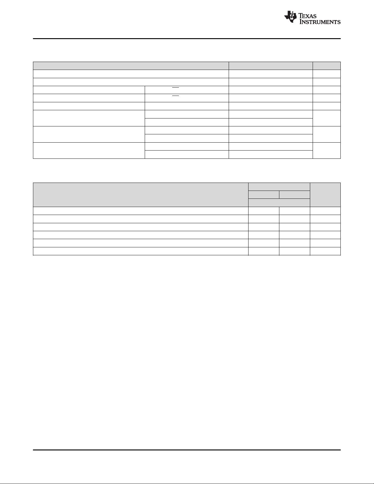
Device Information
(1)
• Each Transceiver Meets or Exceeds the
PART NUMBER PACKAGE BODY SIZE (NOM)
Requirements of TIA/EIA-485 (RS-485) and
SOIC (8) 4.90 mm × 3.91 mm
SN65LBC184,
ISO/IEC 8482:1993(E) Standards
SN75LBC184
PDIP (8) 9.81 mm × 6.35 mm
• Low Disabled Supply Current 300 μA Maximum
(1) For all available packages, see the orderable addendum at
• Pin Compatible With SN75176
the end of the datasheet.
2 Applications
• Industrial Networks
• Utility Meters
• Motor Control
Logic Symbol
NOTE: This symbol is in accordance with ANSI/IEEE Std 91-1984 and IEC Publication 617-12.
1
An IMPORTANT NOTICE at the end of this data sheet addresses availability, warranty, changes, use in safety-critical applications,
intellectual property matters and other important disclaimers. PRODUCTION DATA.
SN65LBC184
,
SN75LBC184
SLLS236I –OCTOBER 1996–REVISED JUNE 2015
www.ti.com
Table of Contents
8.1 Overview ................................................................. 12
1 Features.................................................................. 1
8.2 Functional Block Diagram ....................................... 12
2 Applications ........................................................... 1
8.3 Feature Description................................................. 12
3 Description ............................................................. 1
8.4 Device Functional Modes........................................ 13
4 Revision History..................................................... 2
9 Application and Implementation ........................ 15
5 Pin Configuration and Functions......................... 3
9.1 Application Information............................................ 15
6 Specifications......................................................... 3
9.2 Typical Application ................................................. 15
6.1 Absolute Maximum Ratings ...................................... 3
10 Power Supply Recommendations ..................... 19
6.2 ESD Ratings.............................................................. 3
11 Layout................................................................... 19
6.3 Recommended Operating Conditions....................... 4
11.1 Layout Guidelines ................................................. 19
6.4 Thermal Information.................................................. 4
11.2 Layout Example .................................................... 19
6.5 Electrical Characteristics: Driver ............................... 5
12 Device and Documentation Support ................. 20
6.6 Electrical Characteristics: Receiver .......................... 5
12.1 Related Links ........................................................ 20
6.7 Driver Switching Characteristics ............................... 6
12.2 Community Resources.......................................... 20
6.8 Receiver Switching Characteristics........................... 6
12.3 Trademarks........................................................... 20
6.9 Dissipation Ratings ................................................... 6
12.4 Electrostatic Discharge Caution............................ 20
6.10 Typical Characteristics............................................ 7
12.5 Glossary................................................................ 20
7 Parameter Measurement Information .................. 8
13 Mechanical, Packaging, and Orderable
8 Detailed Description............................................ 12
Information ........................................................... 20
4 Revision History
NOTE: Page numbers for previous revisions may differ from page numbers in the current version.
Changes from Revision H (February 2009) to Revision I Page
• Added Pin Configuration and Functions section, ESD Ratings table, Feature Description section, Device Functional
Modes, Application and Implementation section, Power Supply Recommendations section, Layout section, Device
and Documentation Support section, and Mechanical, Packaging, and Orderable Information section .............................. 1
2 Submit Documentation Feedback Copyright © 1996–2015, Texas Instruments Incorporated
Product Folder Links: SN65LBC184 SN75LBC184
SN65LBC184
,
SN75LBC184
www.ti.com
SLLS236I –OCTOBER 1996–REVISED JUNE 2015
5 Pin Configuration and Functions
D Package, P Package
8-Pin SOIC, 8-Pin PDIP
Top View
Pin Functions
PIN
I/O DESCRIPTION
NAME NO.
A 6 Bus input/output Driver output or receiver input (complementary to B)
B 7 Bus input/output Driver output or receiver input (complementary to A)
D 4 Digital input Driver data input
DE 3 Digital input Active-HIGH driver enable
GND 5 Reference potential Local device ground
R 1 Digital output Receiver data output
RE 2 Digital input Active-LOW receiver enable
V
CC
8 Supply 4.75-V to 5.25-V supply
6 Specifications
6.1 Absolute Maximum Ratings
over operating free-air temperature range (unless otherwise noted)
(1)
MIN MAX UNIT
V
CC
Supply voltage
(2)
–0.5 7 V
Continuous voltage range at any bus terminal –15 15 V
Data input/output voltage –0.3 7 V
I
O
Receiver output current –20 20 mA
Continuous total power dissipation
(3)
Internally Limited
T
stg
Storage temperature 160 °C
(1) Stresses beyond those listed under Absolute Maximum Ratings may cause permanent damage to the device. These are stress ratings
only, and functional operation of the device at these or any other conditions beyond those indicated under Recommended Operating
Conditions is not implied. Exposure to absolute-maximum-rated conditions for extended periods may affect device reliability.
(2) All voltage values, except differential input/output bus voltage, are with respect to network ground terminal.
(3) The driver shuts down at a junction temperature of approximately 160°C. To operate below this temperature, see the Dissipation
Ratings.
6.2 ESD Ratings
VALUE UNIT
A, B, GND ±15000
Human body model (HBM), per ANSI/ESDA/JEDEC
JS-001
(1)
All pins ±3000
Contact discharge (IEC61000-4-2) A, B, GND
(2)
±30000
Electrostatic
V
(ESD)
V
discharge
Air discharge (IEC61000-4-2) A, B, GND
(3)
±15000
All pins (Class 3A) ±8000
All pins (Class 3B) ±200
(1) JEDEC document JEP155 states that 500-V HBM allows safe manufacturing with a standard ESD control process.
(2) GND and bus pin ESD protection is beyond readily available test equipment capabilities for IEC 61000-4-2, EIA/JEDEC test method
A114-A and MIL-STD-883C method 3015. Ratings listed are limits of test equipment; device performance exceeds these limits.
Copyright © 1996–2015, Texas Instruments Incorporated Submit Documentation Feedback 3
Product Folder Links: SN65LBC184 SN75LBC184
SN65LBC184
,
SN75LBC184
SLLS236I –OCTOBER 1996–REVISED JUNE 2015
www.ti.com
6.3 Recommended Operating Conditions
over operating free-air temperature range (unless otherwise noted)
MIN
(1)
TYP MAX UNIT
V
CC
Supply voltage 4.75 5 5.25 V
V
I
or V
IC
Voltage at any bus terminal (separately or common mode) –7 12 V
V
IH
High-level input voltage D, DE, and RE 2 V
V
IL
Low-level input voltage D, DE, and RE 0.8 V
|V
ID
| Differential input voltage 12 V
Driver –60
I
OH
High-level output current mA
Receiver –8
Driver 60
I
OL
Low-level output current mA
Receiver 4
SN75LBC184 0 70
T
A
Operating free-air temperature °C
SN65LBC184 –40 85
(1) The algebraic convention, in which the less-positive (more-negative) limit is designated minimum, is used in this data sheet.
6.4 Thermal Information
SNx5LBC184
THERMAL METRIC
(1)
P [PDIP] D [SOIC] UNIT
8 PINS
R
θJA
Junction-to-ambient thermal resistance 108.7 172.4 °C/W
R
θJC(top)
Junction-to-case (top) thermal resistance 34.8 42.5 °C/W
R
θJB
Junction-to-board thermal resistance 23.6 41.4 °C/W
ψ
JT
Junction-to-top characterization parameter 12 4.6 °C/W
ψ
JB
Junction-to-board characterization parameter 23.5 40.7 °C/W
R
θJC(bot)
Junction-to-case (bottom) thermal resistance N/A N/A °C/W
(1) For more information about traditional and new thermal metrics, see the Semiconductor and IC Package Thermal Metrics application
report, SPRA953.
4 Submit Documentation Feedback Copyright © 1996–2015, Texas Instruments Incorporated
Product Folder Links: SN65LBC184 SN75LBC184
SN65LBC184
,
SN75LBC184
www.ti.com
SLLS236I –OCTOBER 1996–REVISED JUNE 2015
6.5 Electrical Characteristics: Driver
over recommended operating conditions (unless otherwise noted)
ALTERNATE
PARAMETER TEST CONDITIONS MIN TYP
(1)
MAX UNIT
SYMBOLS
DE = RE = 5 V No Load 12 25 mA
I
CC
Supply current NA
DE = 0 V
No Load 175 300 μA
RE = 5 V
High-level input current
I
IH
NA V
I
= 2.4 V 50 μA
(D, DE, RE)
Low-level input current
I
IL
NA V
I
= 0.4 V –50 μA
(D, DE, RE)
V
O
= –7 V –250 –120
Short-circuit output
I
OS
NA V
O
= V
CC
250 mA
current OS
(2)
V
O
= 12 V 250
High-impedance output
I
OZ
NA See Receiver I
I
mA
current
V
O
Output voltage V
oa
, V
ob
I
O
= 0 0 V
CC
V
Peak-to-peak change in
common-mode output
V
OC(PP)
NA See Figure 9 and Figure 10 0.8 V
voltage during state
transitions
Common-mode output
V
OC
|V
os
| See Figure 8 1 3 V
voltage
Magnitude of change,
|ΔV
OC(SS)
| common-mode steady- |V
os
– V
os
| See Figure 10 0.1 V
state output voltage
Magnitude of I
O
= 0 1.5 6 V
|V
OD
| differential output V
o
R
L
= 54 Ω, See Figure 8 1.5 V
voltage |V
A
– V
B
|
Change in differential
Δ|V
OD
| voltage magnitude ||V
t
| – |V
t
|| R
L
= 54 Ω 0.1 V
between logic states
(1) All typical values are measured with T
A
= 25°C and V
CC
= 5 V.
(2) This parameter is measured with only one output being driven at a time.
6.6 Electrical Characteristics: Receiver
over recommended operation conditions (unless otherwise noted)
PARAMETER TEST CONDITIONS MIN TYP
(1)
MAX UNIT
DE = RE = 0 V, No Load 3.9 mA
I
CC
Supply current (total package)
RE = 5 V, DE = 0 V, No Load 300 μA
V
I
= 12 V 250
V
I
= 12 V, V
CC
= 0 250
I
I
Input current Other input = 0 V μA
V
I
= –7 V –200
V
I
= –7 V, V
CC
= 0 –200
I
OZ
High-impedance-state output current V
O
= 0.4 V to 2.4 V ±100 μA
V
hys
Input hysteresis voltage 70 mV
V
IT+
Positive-going input threshold voltage 200 V
V
IT–
Negative-going input threshold voltage –200 mV
V
OH
High-level output voltage I
OH
= –8 mA, See Figure 11 2.8 V
V
OL
Low-level output voltage I
OL
= 4 mA, See Figure 11 0.4 V
(1) All typical values are at V
CC
= 5 V, T
A
= 25°C.
Copyright © 1996–2015, Texas Instruments Incorporated Submit Documentation Feedback 5
Product Folder Links: SN65LBC184 SN75LBC184
剩余28页未读,继续阅读
资源评论
不觉明了
- 粉丝: 3226
- 资源: 5611
上传资源 快速赚钱
- 我的内容管理 展开
- 我的资源 快来上传第一个资源
- 我的收益 登录查看自己的收益
- 我的积分 登录查看自己的积分
- 我的C币 登录后查看C币余额
- 我的收藏
- 我的下载
- 下载帮助
最新资源
- 基于C++实现多目标跟踪系统
- 基于单片机的压力流量报警器(附代码+proteus仿真+论文)
- 基于 Flask 的请假审批管理系统设计与实现
- Test Report TC-24-37 MQ012K0VPY 25.764-28.476MHz.SchDoc
- Java项目-基于Springboot+Vue的校园博客系统的设计与实现(源码+万字LW+部署视频+代码讲解视频+全套软件)
- 服务器虚拟化工具VMware vSphere Client for windows(VMware-viclient-all-6)
- 文件批量改名工具,用于替换/更改字符,更改文件后缀等
- Home Assistant 接入小米空气净化器
- 2024年全国职业院校技能大赛集成电路应用开发赛项竞赛试题(08 卷)
- 2024年全国职业院校技能大赛集成电路应用开发赛项竞赛试题(07 卷)
资源上传下载、课程学习等过程中有任何疑问或建议,欢迎提出宝贵意见哦~我们会及时处理!
点击此处反馈
安全验证
文档复制为VIP权益,开通VIP直接复制
信息提交成功