TI-TMS44409.pdf
需积分: 0 167 浏览量
2022-12-10
23:04:48
上传
评论 4
收藏 414KB PDF 举报

TMS44409, TMS44409P
1048576-WORD BY 4-BIT
DYNAMIC RANDOM-ACCESS MEMORY
SMHS563 – JULY1995
1
POST OFFICE BOX 1443 • HOUSTON, TEXAS 77251–1443
D
Organization...1048576 × 4
D
Single 5-V Power Supply (±10% Tolerance)
D
Performance Ranges:
ACCESS ACCESS ACCESS EDO
TIME TIME TIME CYCLE
(t
RAC
)(t
CAC
)(t
AA
)(t
HPC)
(MAX) (MAX) (MAX) (MIN)
’44409/P-60 60 ns 15 ns 30 ns 25 ns
’44409/P-70 70 ns 18 ns 35 ns 30 ns
’44409/P-80 80 ns 20 ns 40 ns 35 ns
D
Extended Data Out (EDO) Operation
D
CAS-Before-RAS (CBR) Refresh
D
3-State Unlatched Output
D
Low Power Dissipation
D
All Inputs/Outputs and Clocks are
TTL-Compatible
D
Long Refresh Period
– 1 024 Cycle Refresh in 16 ns (max)
– 128 ms on Low Power, Self-Refresh
Version (TMS44409P Only)
D
Operating Free-Air Temperature Range
0°C to 70°C
description
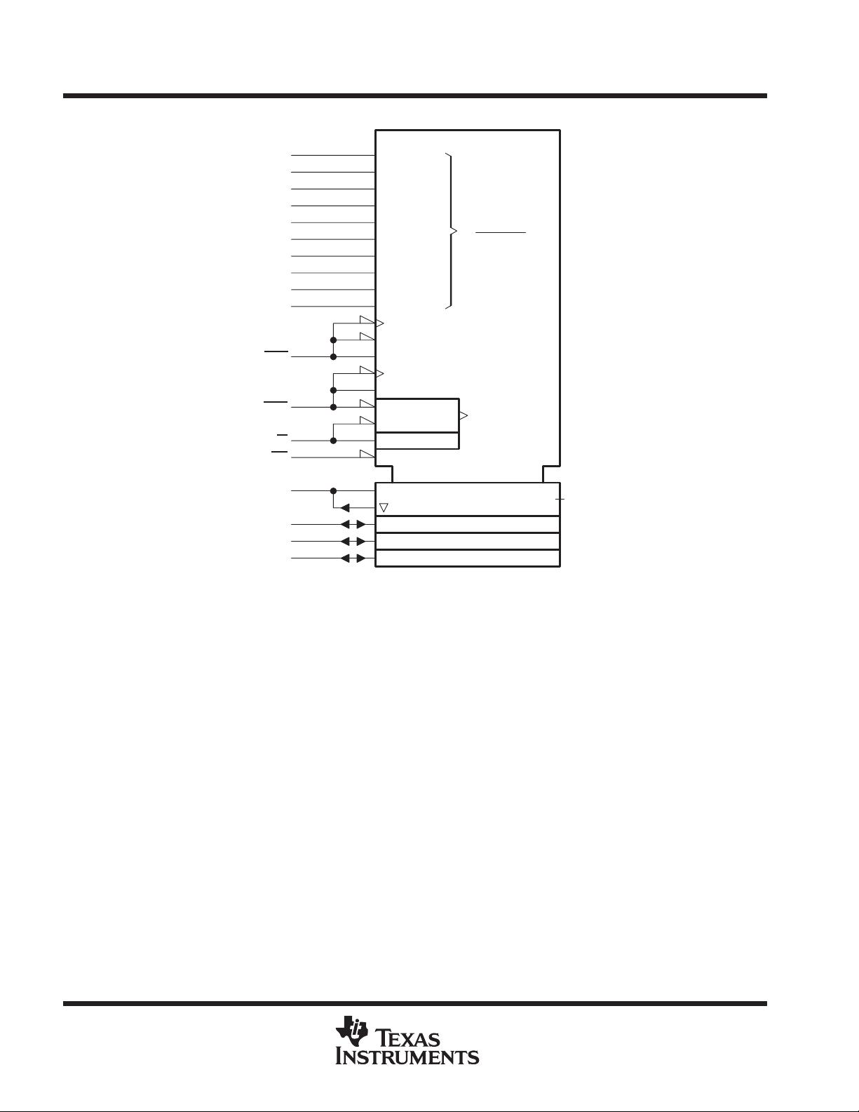
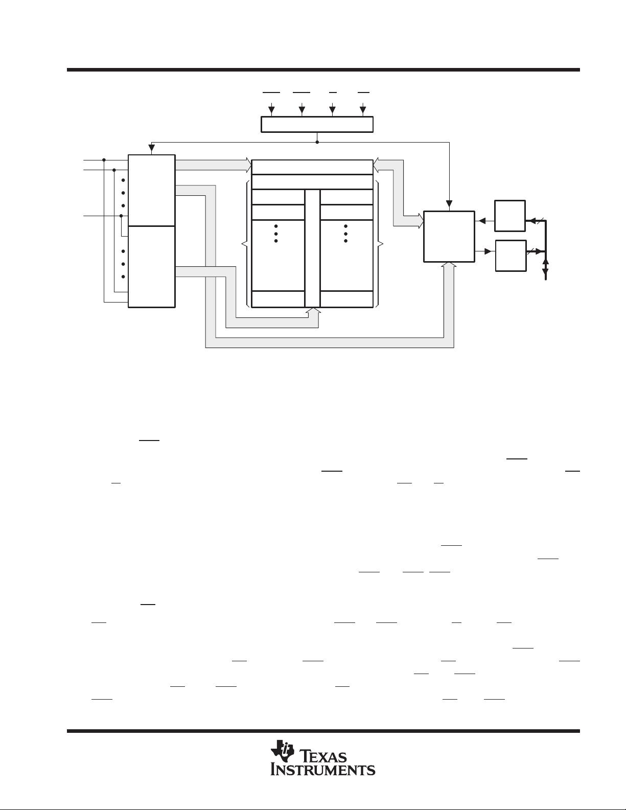
The TMS44409 is a high-speed 4194304-bit
dynamic random-access memory (DRAM) orga-
nized as 1048576 words of four bits each. This
device features maximum RAS
access times of
60 ns, 70 ns and 80 ns. Maximum power
consumption is as low as 385 mW operating and
6 mW standby. All inputs and outputs, including
clocks, are compatible with Series 74 TTL. All addresses and data-in lines are latched on chip to simplify system
design. Data out is unlatched to allow greater system flexibility.
The TMS44409P is a high-speed, low-power, self-refresh version of the TMS44409 DRAM.
All versions of the TMS44409/P are offered in a 300-mil 20/26 J-lead plastic surface-mount SOJ package (DJ
suffix) and a 20/26-lead plastic small outline package (DGA suffix). These devices are characterized for
operation from 0°C to 70°C.
ADVANCE INFORMATION concerns new products in the sampling or
preproduction phase of development. Characteristic data and other
specifications are subject to change without notice.
ADVANCE INFORMATION
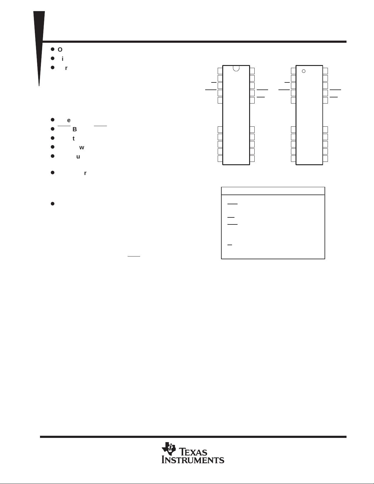
26
25
24
23
22
18
17
16
15
14
1
2
3
4
5
9
10
11
12
13
V
SS
DQ4
DQ3
CAS
OE
A8
A7
A6
A5
A4
DQ1
DQ2
W
RAS
A9
A0
A1
A2
A3
V
CC
26
25
24
23
22
18
17
16
15
14
1
2
3
4
5
9
10
11
12
13
V
SS
DQ4
DQ3
CAS
OE
A8
A7
A6
A5
A4
DQ1
DQ2
W
RAS
A9
A0
A1
A2
A3
V
CC
PIN NOMENCLATURE
A0–A9 Address Inputs
CAS
Column-Address Strobe
DQ1 – DQ4 Data In/ Data Out
OE
Output Enable
RAS
Row-Address Strobe
V
CC
5-V Supply
V
SS
Ground
W
Write Enable
DJ PACKAGE
(TOP VIEW)
DGA PACKAGE
(TOP VIEW)
Copyright 1995, Texas Instruments Incorporated

剩余25页未读,继续阅读


评论0
最新资源