TI-LMH1981.pdf
需积分: 11 15 浏览量
2022-11-30
13:02:12
上传
评论 4
收藏 1.3MB PDF 举报

R
EXT
GND
V
CC1
V
IN
GND
V
CC2
HSOUT
OEOUT
BPOUT
CSOUT
V
CC3
GND
VFOUT
VSOUT
LMH1981
1
2
3
4
5
6
7
14
13
12
11
10
9
8
LMH1981
www.ti.com
SNLS214H –APRIL 2006–REVISED MARCH 2013
LMH1981 Multi-Format Video Sync Separator
Check for Samples: LMH1981
1
FEATURES
DESCRIPTION
The LMH1981 is a high performance multi-format
2
• Standard Analog Video Sync Separation for
sync separator ideal for use in a wide range of video
NTSC, PAL, 480I/P, 576I/P, 720P, and
applications, such as broadcast and professional
1080I/P/PsF from Composite Video (CVBS),
video equipment and HDTV/DTV systems.
S-Video (Y/C), and Component Video
The input accepts standard analog SD/ED/HD video
(YP
B
P
R
/GBR) Interfaces
signals with either bi-level or tri-level sync, and the
• Bi-Level & Tri-Level Sync Compatible
outputs provide all of the critical timing signals in
• Composite, Horizontal, and Vertical Sync
CMOS logic, which swing from rail-to-rail (V
CC
and
Outputs
GND) including Composite, Horizontal, and Vertical
Syncs, Burst/Back Porch Timing, Odd/Even Field,
• Burst/Back Porch Timing, Odd/Even Field, and
and Video Format Outputs. HSync features very low
Video Format Outputs
jitter on its leading (falling) edge, minimizing external
• Superior Jitter Performance on Leading Edge
circuitry needed to clean and reduce jitter in
of HSync
subsequent clock generation stages.
• Automatic Video Format Detection
The LMH1981 automatically detects the input video
• 50% Sync Slicing for Video Inputs from 0.5 V
PP
format, eliminating the need for programming using a
to 2 V
PP
microcontroller, and applies precise 50% sync slicing
to ensure accurate sync extraction at O
H
, even for
• 3.3V to 5V Supply Operation
inputs with irregular amplitude from improper
termination or transmission loss. Its unique Video
APPLICATIONS
Format Output conveys the total horizontal line count
• Broadcast and Professional Video Equipment
per field as an 11-bit binary serial data stream, which
can be decoded by the video system to determine the
• HDTV/DTV Systems
input video format and enable dynamic adjustment of
• Genlock Circuits
system parameters, i.e.: color space or scaler
• Video Capture Devices
conversions. The LMH1981 is available in a 14-pin
• Set-Top Boxes (STB) & Digital Video
TSSOP package and operates over a temperature
range of −40°C to +85°C.
Recorders (DVR)
• Video Displays
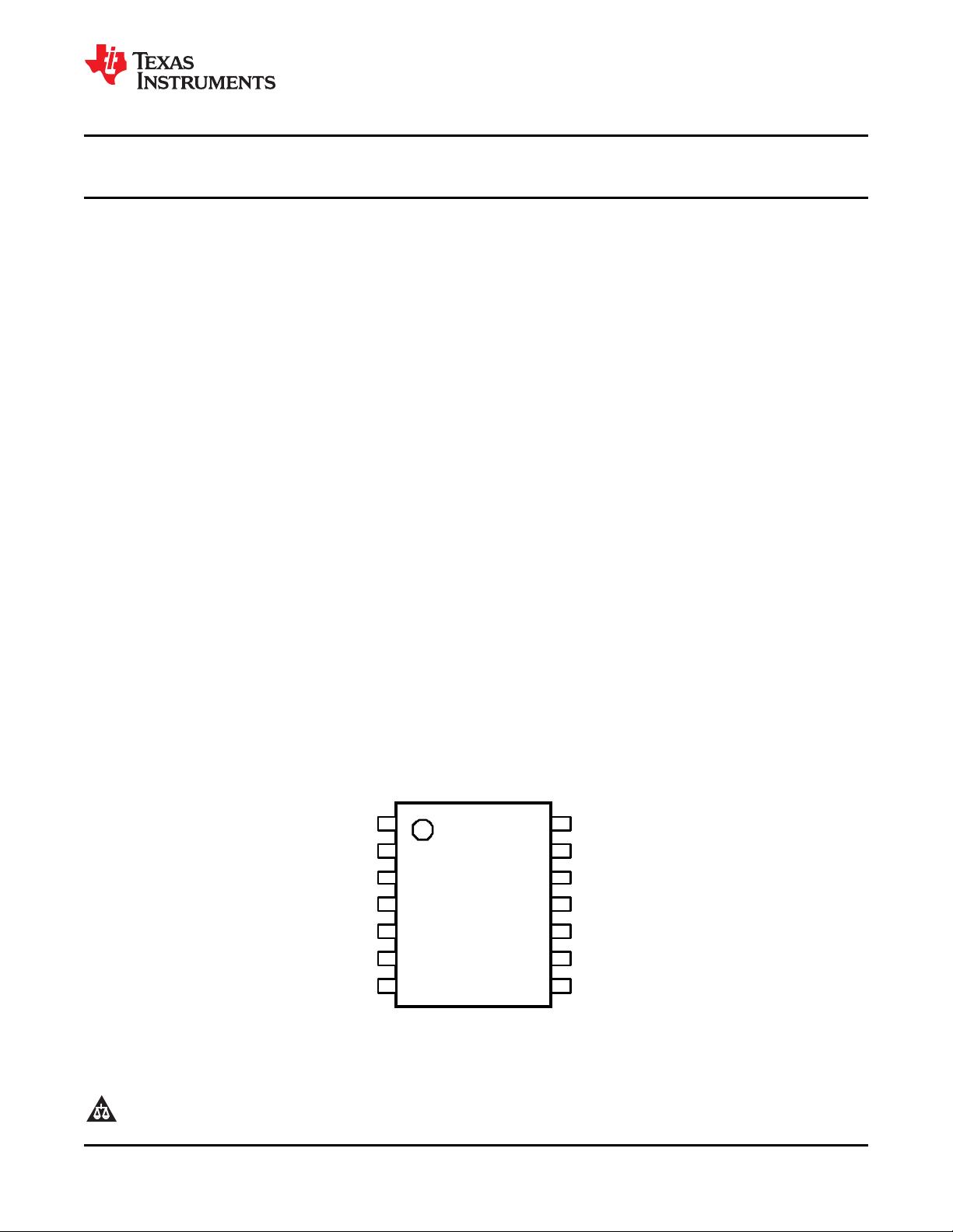
Connection Diagram
Figure 1. 14-Pin TSSOP - Top View
See PW Package
1
Please be aware that an important notice concerning availability, standard warranty, and use in critical applications of
Texas Instruments semiconductor products and disclaimers thereto appears at the end of this data sheet.
2All trademarks are the property of their respective owners.
PRODUCTION DATA information is current as of publication date.
Copyright © 2006–2013, Texas Instruments Incorporated
Products conform to specifications per the terms of the Texas
Instruments standard warranty. Production processing does not
necessarily include testing of all parameters.
剩余25页未读,继续阅读
资源评论


不觉明了
- 粉丝: 3119
- 资源: 5370


最新资源
- 5152单片机proteus仿真和源码用定时器T0的中断控制1位LED闪烁
- 这是用于在 Akka 集群中复制数据的库的早期预览 它是一个复制的内存数据存储,支持低延迟和高可用性 要求
- 基于ketama算法和eredis项目的redis erlang驱动,主要以一致性hash的方式存储数据,做到key的分布式存储
- 2024五一杯B题要点和难点建模解析
- 贪吃蛇小项目的源代码包含snake.c,snake.h,snaketest.c
- 一款极简的截图工具(支持 Win,Mac,Linux)
- 基于SpringBoot + SSM实现的HIS医院信息管理系统
- 基于Springboot+mybatisplus+Layui+mysql制作的图书管理系统
- sql-lap注入靶场
- 803916326552715醒图v9.7.0解锁会员版.apk
资源上传下载、课程学习等过程中有任何疑问或建议,欢迎提出宝贵意见哦~我们会及时处理!
点击此处反馈


