TI-TLV2548-EP.pdf
需积分: 5 132 浏览量
2022-11-27
00:08:45
上传
评论 4
收藏 1.33MB PDF 举报


1
2
3
4
5
6
7
8
9
10
20
19
18
17
16
15
14
13
12
11
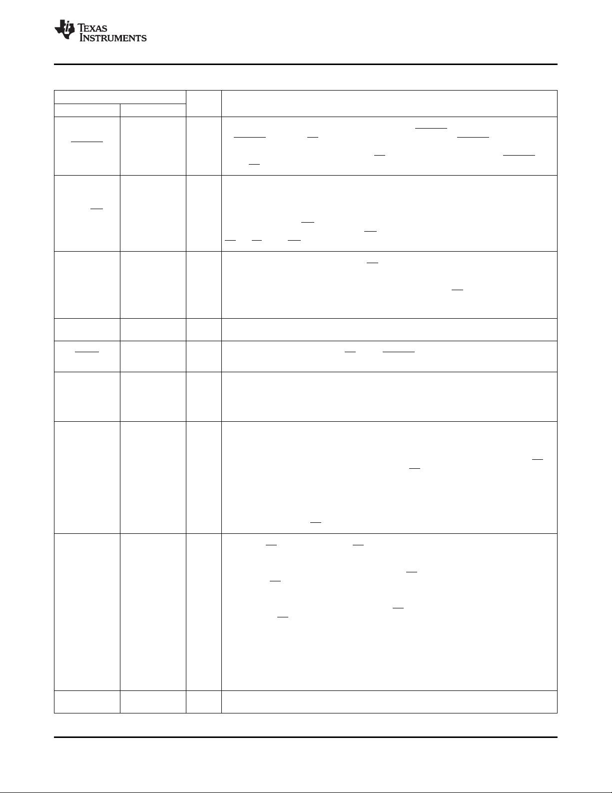
SDO
SDI
SCLK
EOC/(INT
)
V
CC
A0
A1
A2
A3
A4
CS
REFP
REFM
FS
PWDN
GND
CSTART
A7
A6
A5
PW PACKAGE
(TOP VIEW)
TLV2548-EP
www.ti.com
SLAS668 –OCTOBER 2009
3.0-V TO 5.5-V, 12-BIT, 200-KSPS, 4-/8-CHANNEL, LOW-POWER SERIAL
ANALOG-TO-DIGITAL CONVERTER WITH AUTOPOWER-DOWN
Check for Samples: TLV2548-EP
1
FEATURES
SUPPORTS DEFENSE, AEROSPACE,
AND MEDICAL APPLICATIONS
• Maximum Throughput 200-KSPS
• Controlled Baseline
• Built-In Reference, Conversion Clock and
• One Assembly/Test Site
8x FIFO
• One Fabrication Site
• Differential/Integral Nonlinearity Error: ±1.2
• Available in Military (–55°C/125°C)
LSB
Temperature Range
(1)
• Signal-to-Noise and Distortion Ratio: 70 dB,
• Extended Product Life Cycle
f
i
= 12 kHz
• Extended Product-Change Notification
• Spurious Free Dynamic Range: 75 dB,
• Product Traceability
f
i
= 12 kHz
• SPI (CPOL = 0, CPHA = 0)/DSP-Compatible
Serial Interfaces With SCLK up to 20 MHz
• Single Wide Range Supply 3.0 Vdc to 5.5 Vdc
• Analog Input Range 0 V to Supply Voltage
With 500-kHz BW
• Hardware Controlled and Programmable
Sampling Period
• Low Operating Current (1.0 mA at 3.3 V,
2.0 mA at 5.5 V With External Ref, 1.7-mA at
3.3V, 2.4-mA at 5.5-V With Internal Ref)
• Power Down: Software/Hardware
Power-Down Mode (1 μA Max, Ext Ref),
Autopower-Down Mode (1 μA, Ext Ref)
• Programmable Auto-Channel Sweep (1) Custom temperature ranges available
DESCRIPTION
The TLV2548 is a high performance, 12-bit low-power, 3.86-μs, CMOS analog-to-digital converter (ADC) which
operates from a single 3.0-V to 5.5-V power supply. This device has three digital inputs and a 3-state output [chip
select (CS), serial input-output clock (SCLK), serial data input (SDI), and serial data output (SDO)] that provide a
direct 4-wire interface to the serial port of most popular host microprocessors (SPI interface). When interfaced
with a TI DSP, a frame sync (FS) signal is used to indicate the start of a serial data frame.
In addition to a high-speed A/D converter and versatile control capability, this device has an on-chip analog
multiplexer that can select any analog inputs or one of three internal self-test voltages. The sample-and-hold
function is automatically started after the fourth SCLK edge (normal sampling) or can be controlled by a special
pin, CSTART, to extend the sampling period (extended sampling). The normal sampling period can also be
programmed as short (12 SCLKs) or as long (24 SCLKs) to accommodate faster SCLK operation popular among
high-performance signal processors. The TLV2548 is designed to operate with very low power consumption. The
power-saving feature is further enhanced with software/hardware/autopower-down modes and programmable
conversion speeds. The conversion clock (OSC) and reference are built-in. The converter can use the external
SCLK as the source of the conversion clock to achieve higher (up to 2.8 μs when a 20-MHz SCLK is used)
conversion speed. Two different internal reference voltages are available. An optional external reference can also
be used to achieve maximum flexibility.
The TLV2548 is characterized for operation from –55°C to 125°C.
1
Please be aware that an important notice concerning availability, standard warranty, and use in critical applications of Texas
Instruments semiconductor products and disclaimers thereto appears at the end of this data sheet.
PRODUCTION DATA information is current as of publication date.
Copyright © 2009, Texas Instruments Incorporated
Products conform to specifications per the terms of the Texas
Instruments standard warranty. Production processing does not
necessarily include testing of all parameters.


剩余37页未读,继续阅读
资源评论


不觉明了
- 粉丝: 3163
- 资源: 5419


