没有合适的资源?快使用搜索试试~ 我知道了~
MAX1795EUA maxim 美信芯片 电子元器件中文版规格手册.pdf
需积分: 5 0 下载量 29 浏览量
2023-06-07
10:02:12
上传
评论
收藏 1.96MB PDF 举报
温馨提示
试读
14页
MAX1795EUA maxim 美信芯片 电子元器件中文版规格手册
资源推荐
资源详情
资源评论
General Description
The MAX1795/MAX1796/MAX1797 are high-efficiency,
step-up DC-DC converters intended for small portable
hand-held devices. These devices feature Maxim’s True
Shutdown™ circuitry, which fully disconnects the out-
put from the input in shutdown, improves efficiency,
and eliminates costly external components. All three
devices also feature Maxim’s proprietary LX-damping
circuitry for reduced EMI in noise-sensitive applications.
For additional in-system flexibility, a battery monitoring
comparator (LBI/LBO) remains active even when the
DC-DC converter is in shutdown.
The input voltage range is +0.7V to V
OUT
, where V
OUT
can be set from +2V to +5.5V. Startup is guaranteed
from +0.85V. The MAX1795/MAX1796/MAX1797 have a
preset, pin-selectable 5V or 3.3V output. The output can
also be adjusted to other voltages, using two external
resistors. The three devices differ only in their current
limits, allowing optimization of external components for
different loads: The MAX1795, MAX1796, and MAX1797
have current limits of 0.25A, 0.5A, and 1A, respectively.
All devices are packaged in a compact, 8-pin μMAX
package that is only 1.09mm tall and half the size of an
8-pin SO.
Applications
● Portable Digital Audio Players
● PDAs/Palmtops
● Wireless Handsets
● Portable Terminals
Features
● > 95% Efficiency
● True-Shutdown Circuitry
• Output Disconnects from Input in Shutdown
• No External Schottky Diode Needed
● 25μA Quiescent Supply Current
● Low-Noise Antiringing Feature
● LBI/LBO Comparator Enabled in Shutdown
● 2μA Shutdown Current
● 8-Pin μMAX Package
19-1798; Rev 0; 12/00
True Shutdown is a trademark of Maxim Integrated Products.
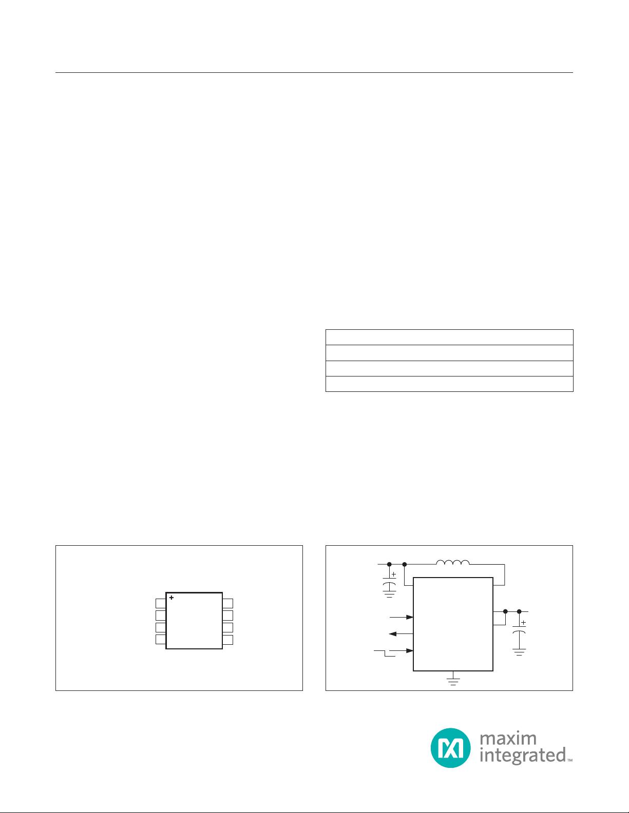
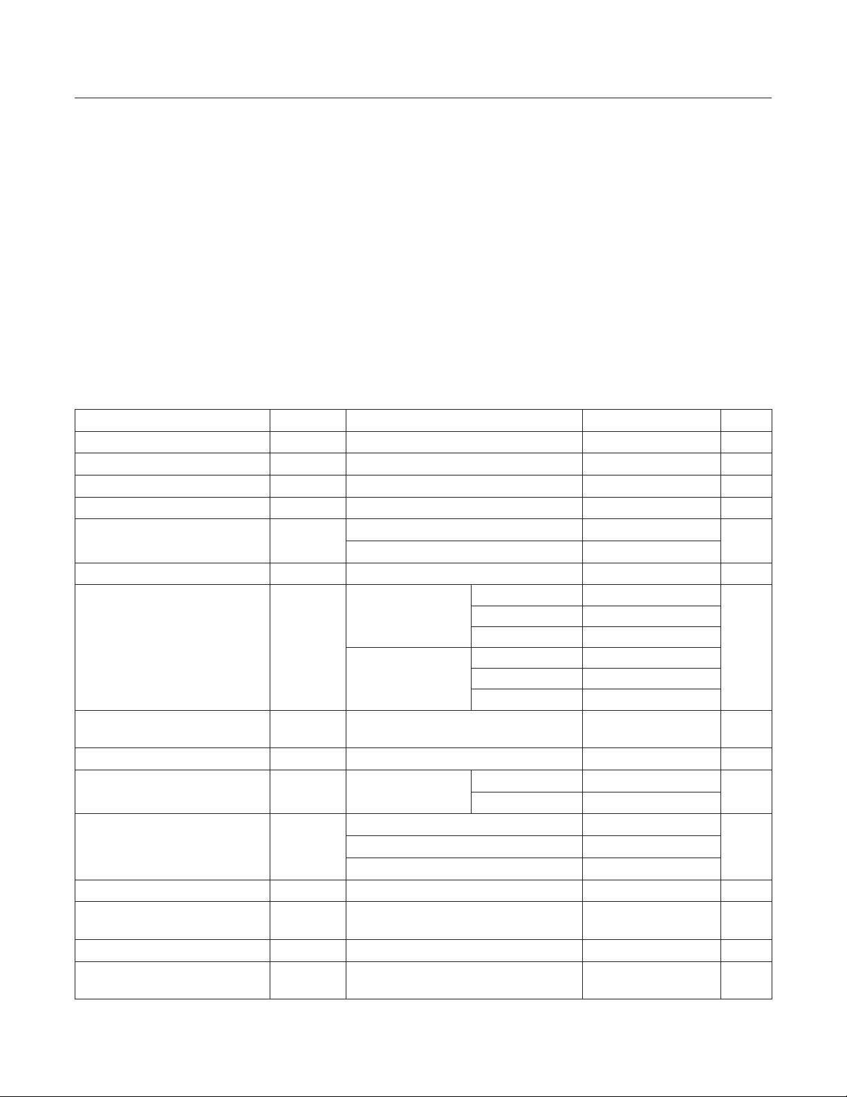
Pin Conguration Typical Operating Circuit
Ordering Information
PART TEMP RANGE PIN-PACKAGE
MAX1795EUA -40°C to +85°C 8 μMAX
MAX1796EUA -40°C to +85°C 8 μMAX
MAX1797EUA -40°C to +85°C 8 μMAX
1
2
3
4
8
7
6
5
BATT
OUT
LX
GND
LBO
FB
LBI
MAX1795
MAX1796
MAX1797
µMAX
TOP VIEW
SHDN
GND
LBI
LBO
BATT
FB
LX
OUT
SHDN
OUT
IN
0.7V TO
5.5V
ON
OFF
MAX1795
MAX1796
MAX1797
MAX1795/MAX1796/
MAX1797
Low-Supply Current, Step-Up DC-DC Converters
with True Shutdown
OUT, LX, SHDN, LBI, LBO, BATT to GND ..............-0.3V to +6V
FB ........................................................... -0.3V to (V
OUT
+ 0.3V)
I
LX
, I
OUT
............................................................................. ±1.5A
Output Short-Circuit Duration .................................................. 5s
Continuous Power Dissipation
8-Pin μMAX (derate 4.1mW/°C above +70°C) ............330mW
Operating Temperature Range ........................... -40°C to +85°C
Junction Temperature ...................................................... +150°C
Storage Temperature Range ............................ -65°C to +150°C
Lead Temperature (soldering, 10s) .................................+300°C
(V
BATT
= +2V, OUT = FB (V
OUT
= +3.3V), SHDN = LBI = GND, T
A
= 0°C to +85°C, unless otherwise noted. Typical values are at
T
A
= +25°C.)
Absolute Maximum Ratings
Stresses beyond those listed under “Absolute Maximum Ratings” may cause permanent damage to the device. These are stress ratings only, and functional operation of the device at these
or any other conditions beyond those indicated in the operational sections of the specifications is not implied. Exposure to absolute maximum rating conditions for extended periods may affect
device reliability.
Electrical Characteristics
PARAMETER SYMBOL CONDITIONS MIN TYP MAX UNITS
Minimum Input Voltage After startup 0.7 V
Operating Voltage V
BATT
(Note 1) 1.0 5.5 V
Startup Voltage T
A
= +25°C, R
L
= 3kΩ 0.85 1.0 V
Startup Voltage Tempco -2.2 mV/°C
Output Voltage V
OUT
FB = OUT 3.17 3.3 3.43
V
FB = GND 4.80 5.0 5.20
Adjustable Output Voltage Range 2.0 5.5 V
Steady-State Output Current I
OUT
BATT = +2V,
FB = OUT
(V
OUT
= +3.3V)
MAX1795 100 180
mA
MAX1796 200 300
MAX1797 400 550
BATT = +2V,
FB = GND
(V
OUT
= +5.0V)
MAX1795 50 120
MAX1796 100 200
MAX1797 250 370
Feedback Set-Point Voltage
(Adjustable Mode)
V
FB
V
OUT
= +2V to +5.5V 1.20 1.24 1.28 V
Feedback Input Current I
FB
V
FB
= +1.24V 4 100 nA
Internal NFET, PFET
On-Resistance
R
DS(ON)
V
OUT
= +3.3V,
I
LX
= 100mA
NFET 0.17 0.3
Ω
PFET 0.27 0.45
LX Switch Current Limit
(NFET only)
I
LIM
MAX1795 0.2 0.25 0.35
AMAX1796 0.4 0.5 0.625
MAX1797 0.8 1.0 1.25
LX Leakage Current I
LEAK
V
LX
= 0 and +5.5V, V
OUT
= +5.5V 0.2 µA
Synchronous Rectier Turn-Off
Current Limit
25 mA
Damping Switch On-Resistance R
DAMP
100 200 400 Ω
Operating Current into OUT
(Note 2)
V
FB
= +1.4V 25 45 µA
MAX1795/MAX1796/
MAX1797
Low-Supply Current, Step-Up DC-DC Converters
with True Shutdown
www.maximintegrated.com
Maxim Integrated
│
2
(V
BATT
= +2V, OUT = FB (V
OUT
= +3.3V), SHDN = LBI = GND, T
A
= -40°C to +85°C, unless otherwise noted.) (Note 3)
(V
BATT
= +2V, OUT = FB (V
OUT
= +3.3V), SHDN = LBI = GND, T
A
= 0°C to +85°C, unless otherwise noted. Typical values are at
T
A
= +25°C.)
Electrical Characteristics
Electrical Characteristics (continued)
PARAMETER SYMBOL CONDITIONS MIN TYP MAX UNITS
Operating Current into BATT V
FB
= +1.4V, V
LBI
= +1V 2 4 µA
Shutdown Current into BATT SHDN = BATT, V
LBI
= +1V 2 4 µA
LX Switch MaxImum On-Time t
ON
V
FB
= +1V, if current limit not reached 3 4 5 µs
LX Switch Minimum Off-Time t
OFF
V
FB
= +1V 0.8 1 1.2 µs
LBI Threshold Voltage Falling V
LBI
V
BATT
= +2V 0.8 0.85 0.90
V
V
BATT
= LBI 0.875 0.925 0.975
LBI Hysteresis 25 mV
LBI Input Current I
LBI
V
LBI
= +0.8V 9 100 nA
LBO Low Output Voltage
V
BATT
= V
LBI
= +0.975V,
sinking 20µA (50Ω typ)
0.1
V
V
BATT
= V
LBI
= +1.1V,
sinking 100µA (25Ω typ)
0.1
LBO Off-Leakage Current V
LBO
= +5.5V 1 100 nA
SHDN Input Voltage
V
IL
0.2 x
V
BATT
V
V
IH
0.8 x
V
BATT
Shutdown Input Current V
SHDN
= 0 and +5.5V 100 nA
PARAMETER SYMBOL CONDITIONS MIN MAX UNITS
Operating Voltage V
BATT
Note 1 1.0 5.5 V
Output Voltage V
OUT
FB = OUT 3.13 3.47
V
FB = GND 4.75 5.25
Adjustable Output Voltage Range 2.0 5.5 V
Steady-State Output Current
(Note 1)
I
OUT
FB = OUT
(V
OUT
= +3.3V)
MAX1795 100
mA
MAX1796 200
MAX1797 400
FB = GND
(V
OUT
= +5.0V)
MAX1795 60
MAX1796 125
MAX1797 250
Feedback Set-Point Voltage
(Adjustable Mode)
V
FB
V
OUT
= +2V to +5.5V 1.19 1.29 V
Feedback Input Current I
FB
V
FB
= +1.25V 100 nA
MAX1795/MAX1796/
MAX1797
Low-Supply Current, Step-Up DC-DC Converters
with True Shutdown
www.maximintegrated.com
Maxim Integrated
│
3
剩余13页未读,继续阅读
资源评论
芯脉芯城
- 粉丝: 3
- 资源: 4031
上传资源 快速赚钱
- 我的内容管理 展开
- 我的资源 快来上传第一个资源
- 我的收益 登录查看自己的收益
- 我的积分 登录查看自己的积分
- 我的C币 登录后查看C币余额
- 我的收藏
- 我的下载
- 下载帮助
安全验证
文档复制为VIP权益,开通VIP直接复制
信息提交成功