没有合适的资源?快使用搜索试试~ 我知道了~
MAX1678EUA maxim 美信芯片 电子元器件中文版规格手册.pdf
需积分: 5 0 下载量 68 浏览量
2023-06-06
10:21:17
上传
评论
收藏 165KB PDF 举报
温馨提示
试读
13页
MAX1678EUA maxim 美信芯片 电子元器件中文版规格手册
资源推荐
资源详情
资源评论
For free samples & the latest literature: http://www.maxim-ic.com, or phone 1-800-998-8800.
For small orders, phone 408-737-7600 ext. 3468.
General Description
The MAX1678 is a high-efficiency, low-voltage, syn-
chronous-rectified, step-up DC-DC converter intended
for use in devices powered by 1 to 3-cell alkaline,
NiMH, or NiCd batteries or a 1-cell lithium battery. It
guarantees a 0.87V start-up voltage and features a low
37µA quiescent supply current.
The device includes a 1Ω, N-channel MOSFET power
switch, a synchronous rectifier that acts as the catch
diode, a reference, pulse-frequency-modulation (PFM)
control circuitry, and circuitry to reduce inductor ring-
ing—all in an ultra-small, 1.1mm-high µMAX package.
The output voltage is preset to 3.3V or can be adjusted
from +2V to +5.5V using only two resistors. Efficiencies
up to 90% are achieved for loads up to 50mA. The
device also features an independent undervoltage
comparator (PFI/PFO) and a logic-controlled 2µA shut-
down mode.
Applications
Pagers
Remote Controls
Pointing Devices
Personal Medical Monitors
Single-Cell Battery-Powered Devices
Features
♦ 0.87V Guaranteed Start-Up
♦ Up to 90% Efficiency
♦ Built-In Synchronous Rectifier (no external diode)
♦ Ultra-Small µMAX Package, 1.1mm High
♦ 37µA Quiescent Current (85µA from 1.5V battery)
♦ 2µA Logic-Controlled Shutdown
♦ Power-Fail Detector
♦ Dual Mode™ Output: Fixed 3.3V
Adjustable 2V to 5.5V
♦ 45mA Output Current at 3.3V for 1-Cell Input
♦ 90mA Output Current at 3.3V for 2-Cell Input
♦ Inductor-Damping Switch Suppresses EMI
MAX1678
1-Cell to 2-Cell, Low-Noise,
High-Efficiency, Step-Up DC-DC Converter
________________________________________________________________
Maxim Integrated Products
1
1
2
3
4
8
7
6
5
OUT
LX
GND
FBSHDN
PFO
PFI
BATT
MAX1678
µMAX
TOP VIEW
OUT
OUTPUT
3.3V
INPUT
0.87V TO V
OUT
ON
LOW-BATTERY
DETECTOR INPUT
LOW-BATTERY
DETECTOR OUTPUT
OFF
PFO
BATT
LX
MAX1678
SHDN
PFI
GND FB
Typical Operating Circuit
19-1381; Rev 0; 7/98
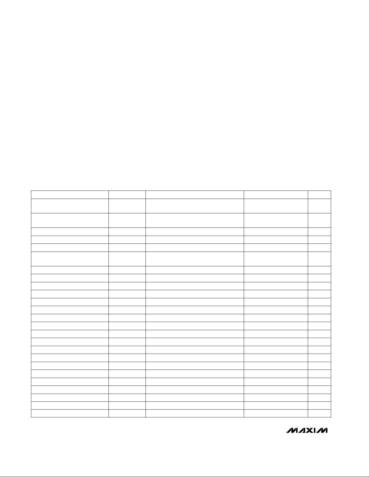
PART
MAX1678EUA -40°C to +85°C
TEMP. RANGE PIN-PACKAGE
8 µMAX
EVALUATION KIT
AVAILABLE
Note: To order these devices shipped in tape-and-reel, add a -T
to the part number.
Pin Configuration
Ordering Information
Dual Mode is a trademark of Maxim Integrated Products.
MAX1678
1-Cell to 2-Cell, Low-Noise,
High-Efficiency, Step-Up DC-DC Converter
2 _______________________________________________________________________________________
ABSOLUTE MAXIMUM RATINGS
ELECTRICAL CHARACTERISTICS
(V
BATT
= V
SHDN
= 1.3V, I
LOAD
= 0, FB = GND, T
A
= 0°C to +85°C, unless otherwise noted. Typical values are at T
A
= +25°C.)
Stresses beyond those listed under “Absolute Maximum Ratings” may cause permanent damage to the device. These are stress ratings only, and functional
operation of the device at these or any other conditions beyond those indicated in the operational sections of the specifications is not implied. Exposure to
absolute maximum rating conditions for extended periods may affect device reliability.
Note 1: The reverse battery current is measured from the
Typical Operating Circuit’s
input terminal to GND when the battery is con-
nected backward. A reverse current of 220mA will not exceed package dissipation limits but, if left for an extended time
(more than 10 minutes), may degrade performance.
BATT, OUT,LX, SHDN to GND ..............................-0.3V to +6.0V
OUT, LX Current.......................................................................1A
FB, PFI, PFO to GND ................................-0.3V to (V
OUT
+ 0.3V)
Reverse Battery Current (T
A
= +25°C) (Note 1) ...............220mA
Continuous Power Dissipation (T
A
= +70°C)
µMAX (derate 4.1mW/°C above +70°C) .......................330mW
Operating Temperature Range ...........................-40°C to +85°C
Junction Temperature......................................................+150°C
Storage Temperature Range .............................-65°C to +165°C
Lead Temperature (soldering, 10sec) .............................+300°C
V
PFI
= 650mV, V
PFO
= 6V
R
L
= 3kΩ, T
A
= +25°C
V
PFI
= 0, V
OUT
= 3.3V, I
SINK
= 1mA
V
PFI
= 650mV
Falling PFI hysteresis 2%
V
FB
= 1.3V
I
LOAD
= 20mA, V
BATT
= 2.5V (Figure 7)
V
BATT
= 1V
I
DIODE
= 100mA, P-channel switch off
V
OUT
= 3.5V
V
OUT
= 3.3V
V
OUT
= 3.3V
V
FB
< 0.1V
External feedback
V
OUT
= 3.5V
External feedback
0.9V < V
BATT
< 3.3V (t
ON
= K / V
BATT
)
CONDITIONS
V0.8 x V
BATT
V
IH
SHDN Input High Voltage
V0.2 x V
BATT
V
IL
SHDN Input Low Voltage
µA0.01 1PFO Leakage Current
V0.04 0.4V
OL
PFO Low Output Voltage
nA0.1 10PFI Input Current
mV590 614 632V
IL,PFI
PFI Trip Voltage
nA0.1 10FB Input Current
%90
η
Efficiency
µA2 3.5I
SHDN,BATT
Shutdown Current into BATT
µA0.1 1I
SHDN,OUT
Shutdown Current into OUT
µA4 8I
Q,BATT
Quiescent Current into BATT
µA37 65I
Q,OUT
Quiescent Current into OUT
V-µs5.60 8 11.2KOn-Time Constant
V0.87Start-Up Voltage (Note 2)
V5.5V
BATT(MAX)
V0.7V
BATT(MIN)
Minimum Operating Input
Voltage
Maximum Operating Input
Voltage
mA550I
LX(MAX)
Maximum Peak LX Current
V0.8P-Channel Catch Diode Voltage
Ω1.5 2.2P-Channel On-Resistance
Ω1 1.5N-Channel On-Resistance
mV/°C-2Start-Up Voltage Tempco
V3.16 3.3 3.44V
OUT
Output Voltage (Fixed Mode)
V2.0 5.5
Output Voltage Range
(Adjustable Mode)
V1.19 1.23 1.26V
FB
FB Set Voltage
UNITSMIN TYP MAXSYMBOLPARAMETER
SHDN = GND or BATT
nA0.1 10
SHDN Input Current
MAX1678
1-Cell to 2-Cell, Low-Noise,
High-Efficiency, Step-Up DC-DC Converter
_______________________________________________________________________________________ 3
ELECTRICAL CHARACTERISTICS
(V
BATT
= V
SHDN
= 1.3V, I
LOAD
= 0, FB = GND, T
A
= -40°C to +85°C, unless otherwise noted.) (Note 3)
V
PFI
= 650mV, V
PFO
= 6V
V
PFI
= 0, V
OUT
= 3.3V, I
SINK
= 1mA
V
PFI
= 650mV
Falling PFI hysteresis 2%
V
FB
= 1.3V
V
BATT
= 1V
V
OUT
= 3.5V
V
OUT
= 3.3V
V
OUT
= 3.3V
V
FB
< 0.1V
External feedback
V
OUT
= 3.5V
External feedback
0.9V < V
BATT
< 3.3V (t
ON
= K / V
BATT
)
CONDITIONS
V0.8 x V
BATT
V
IH
SHDN Input High Voltage
V0.2 x V
BATT
V
IL
SHDN Input Low Voltage
µA1PFO Leakage Current
V0.4V
OL
PFO Low Output Voltage
nA10PFI Input Current
mV580 642V
IL,PFI
PFI Trip Voltage
nA10FB Input Current
µA3.5I
SHDN,BATT
Shutdown Current into BATT
µA1I
SHDN,OUT
Shutdown Current into OUT
µA8I
Q,BATT
Quiescent Current into BATT
µA65I
Q,OUT
Quiescent Current into OUT
V-µs5.60 11.2KOn-Time Constant
V5.5V
BATT(MAX)
Maximum Operating Input
Voltage
Ω2.2P-Channel On-Resistance
Ω1.5N-Channel On-Resistance
V3.12 3.48V
OUT
Output Voltage (Fixed Mode)
V2.0 5.5
Output Voltage Range
(Adjustable Mode)
V1.17 1.28V
FB
FB Set Voltage
UNITSMIN MAXSYMBOLPARAMETER
SHDN = GND or BATT
nA10
SHDN Input Current
Note 2: Start-up is guaranteed by correlation to measurements of device parameters (i.e., switch on-resistance, on-time, off-time,
and output voltage trip point).
Note 3: Specifications to -40°C are guaranteed by design and not production tested.
剩余12页未读,继续阅读
资源评论
芯脉芯城
- 粉丝: 3
- 资源: 4031
上传资源 快速赚钱
- 我的内容管理 展开
- 我的资源 快来上传第一个资源
- 我的收益 登录查看自己的收益
- 我的积分 登录查看自己的积分
- 我的C币 登录后查看C币余额
- 我的收藏
- 我的下载
- 下载帮助
安全验证
文档复制为VIP权益,开通VIP直接复制
信息提交成功