


1
System-level models of Analog Devices RF Transceivers
In this add-on package, you find the system-level models of two Agile RF Transceivers from Analog Devices:
AD9361 and AD9371. These models are co-developed and validated using lab measurements by MathWorks and
Analog Devices. The archive contains a library of models and a set of testbench examples.
To run these models, you will need the following MathWorks products:
− MATLAB®
− Simulink®
− RF Blockset™
− RF Toolbox™
− Signal Processing Toolbox™
− DSP System Toolbox™
− Communications System Toolbox™
− Fixed-Point Designer™
− Stateflow® - required for the AD9361 and AD9371 receiver models
− Control System Toolbox™ - required for AD9371 receiver models
− LTE System Toolbox™ - required to run AD9371 standard compliant LTE testbenches
The AD9361 models are available starting from R2014a, and are regularly updated to the latest release. To
configure and run these models, the add-on package automatically installs “AD9361 Filter Wizard”.
The AD9371 models are available starting from R2017a, and are regularly updated to the latest release. To
configure and run these models, the add-on package automatically installs “AD9371 Filter Wizard” (Profile
Generator).
If you don’t have the required products, you can contact your account manager, or ask for a trial on MathWorks
website: https://www.mathworks.com/programs/trials/trial_request.html
More information on the transceiver architecture and functionality can be found on ADI web page. See the
section “more information” at the end of this document for some useful links.
For questions on the models, please contact support@mathworks.com

2
Table of Contents
System-level models of Analog Devices RF Transceivers .............................................................................. 1
AD9361 Introduction ..................................................................................................................................... 5
AD9361 Transmitter Model ........................................................................................................................... 6
Digital Up-Conversion Filters ................................................................................................................. 7
Analog Filters ......................................................................................................................................... 8
RF Transmitter ....................................................................................................................................... 8
AD9361 Receiver Model ................................................................................................................................ 9
RF Receiver .......................................................................................................................................... 11
Analog Filters ....................................................................................................................................... 12
Analog to Digital Converter ................................................................................................................. 12
Digital Down-Conversion Filters .......................................................................................................... 12
Received Signal Strength Indicator ...................................................................................................... 12
Automatic Gain Control ....................................................................................................................... 13
Gain Table and RF imperfections ......................................................................................................... 14
AD9361 Transmitter Testbench .................................................................................................................. 16
Signal Source ....................................................................................................................................... 16
Local Oscillator .................................................................................................................................... 17
Signal Visualization .............................................................................................................................. 17
AD9361 Receiver Testbench ........................................................................................................................ 17
Signal Source ....................................................................................................................................... 17
Local Oscillator .................................................................................................................................... 18
Signal Visualization .............................................................................................................................. 18
AD9361 Transmitter + Receiver QPSK Testbench ....................................................................................... 18
QPSK Transmitter ................................................................................................................................ 19
Multipath Rayleigh fading channel ...................................................................................................... 19
QPSK Receiver ...................................................................................................................................... 19
Local Oscillator .................................................................................................................................... 20
Signal Visualization .............................................................................................................................. 20
AD9361 Receiver Testbench with Out of Band Interfering Signal ............................................................... 20
Signal Source ....................................................................................................................................... 21
Local Oscillator .................................................................................................................................... 21
AD9361 Receiver ................................................................................................................................. 21
Signal Visualization .............................................................................................................................. 22
More information on AD9361 ..................................................................................................................... 23
AD9371 Introduction ................................................................................................................................... 24

3
AD9371 Transmitter Model ......................................................................................................................... 25
Digital Up-Conversion Filters ............................................................................................................... 26
Analog Filters ....................................................................................................................................... 26
RF Transmitter ..................................................................................................................................... 27
AD9371 Receiver Model .............................................................................................................................. 28
RF Receiver .......................................................................................................................................... 30
Analog Filters ....................................................................................................................................... 30
Analog to Digital Converter ................................................................................................................. 30
Digital Down-Conversion Filters .......................................................................................................... 30
Received Signal Strength Indicator ...................................................................................................... 31
Automatic Gain Control ....................................................................................................................... 31
Gain Table ............................................................................................................................................ 32
AD9371 Observer Model ............................................................................................................................. 33
RF Receiver .......................................................................................................................................... 35
Analog Filters ....................................................................................................................................... 35
Analog to Digital Converter ................................................................................................................. 35
Digital Down-Conversion Filters .......................................................................................................... 35
Automatic Gain Control ....................................................................................................................... 36
Gain Table ............................................................................................................................................ 36
AD9371 Sniffer Model ................................................................................................................................. 37
RF Receiver .......................................................................................................................................... 39
Analog Filters ....................................................................................................................................... 39
Analog to Digital Converter ................................................................................................................. 39
Digital Down-Conversion Filters .......................................................................................................... 39
Received Signal Strength Indicator ...................................................................................................... 40
Automatic Gain Control ....................................................................................................................... 40
Gain Table ............................................................................................................................................ 41
AD9371 Transmitter Testbench .................................................................................................................. 42
Signal Source ....................................................................................................................................... 42
Local Oscillator .................................................................................................................................... 43
Signal Visualization .............................................................................................................................. 43
AD9371 Receiver, Observer and Sniffer Testbenches ................................................................................. 43
Signal Source ....................................................................................................................................... 44
Local Oscillator .................................................................................................................................... 44
Signal Visualization .............................................................................................................................. 44
AD9371 Transmitter + Receiver QPSK Testbench ....................................................................................... 45

4
QPSK Transmitter ................................................................................................................................ 45
Local Oscillators ................................................................................................................................... 45
AD9371 Transmitter and Receiver ...................................................................................................... 45
QPSK Receiver ...................................................................................................................................... 46
Signal Visualization .............................................................................................................................. 46
AD9371 Transmitter + PA + DPD ................................................................................................................. 47
QPSK Transmitter ................................................................................................................................ 47
Local Oscillator .................................................................................................................................... 47
AD9371 Transmitter and Observer ..................................................................................................... 47
Power Amplifier Model ....................................................................................................................... 48
Adaptive DPD Algorithm ...................................................................................................................... 48
QPSK Receiver ...................................................................................................................................... 48
Signal Visualization .............................................................................................................................. 48
LTE Standard Compliant Testbenches ......................................................................................................... 49
More information on AD9371 ..................................................................................................................... 49
5
AD9361 Introduction
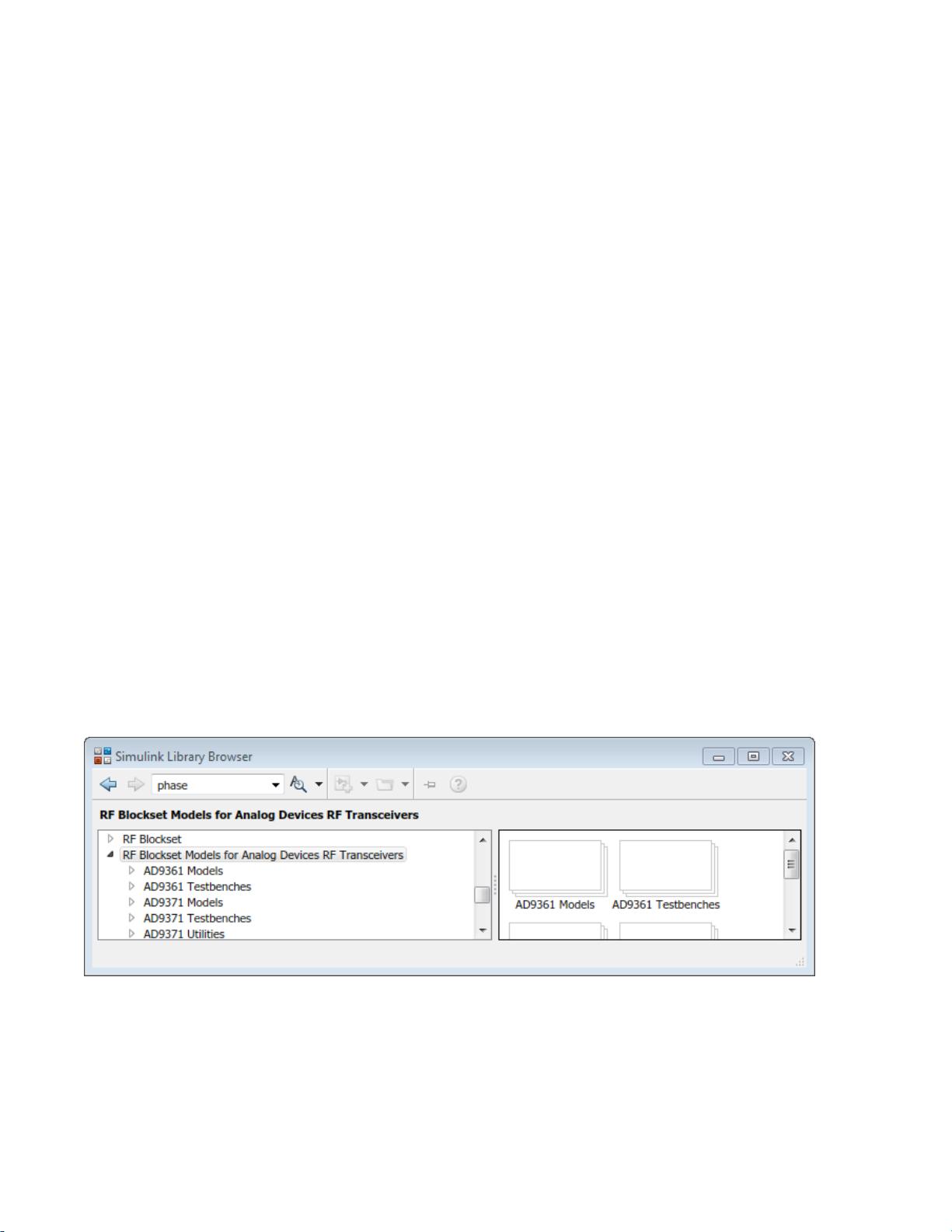
AD9361 transmitter and receiver models are available after the installation of the add-on package. When
opening “RF Blockset models for Analog Devices RF Transceivers” from the Simulink library browser you will find
a set of testbenches (AD9361 Testbenches) and a library with the transmitter and receiver models (AD9361
Models). Alternatively, you can type the following in the MATLAB Command Window:
>> open ad9361_testbenches
>> open ad9361_models
You can inspect the models and the testbenches, and modify them if needed. When you instantiate a model
from the library ad9361_models, you should disable the library link before modifying its content. You don’t
need to disable the link to configure the filters using the AD9361 Filter Wizard.
The library with the ad9361_testbenches includes a set of examples to rapidly get started with testing the
models and using them in realistic scenarios:
- ad9361_tx: LTE (5MHz, 10MHz, and 20MHz), and CW test signals for RF transmitter
- ad9361_rx: LTE (5MHz, 10MHz, and 20MHz), and CW test signals RF receiver, including in-band interferer
- ad9361_rx_interferer: LTE (5MHz, 10MHz, and 20MHz), and CW test signals RF receiver, including
out-of-band interferer
- ad9361_QPSK: QPSK test signal for RF transmitter + RF receiver, including multipath fading
The LTE waveforms in the ad9361_tx and ad9361_rx testbenches are not standard compliant, and
therefore do not require LTE System Toolbox.
The following chapter first describes the transmitter and the receiver models, and then describes the
testbenches in which the models are used. All models and testbenches are white-boxes that the you can modify.


