IRFB4321PBF INFINEON 英飞凌芯片 中文版规格书手册.pdf
需积分: 5 89 浏览量
2023-06-05
10:56:16
上传
评论
收藏 283KB PDF 举报

12/9/10
www.irf.com 1
HEXFET
®
Power MOSFET
IRFB4321PbF
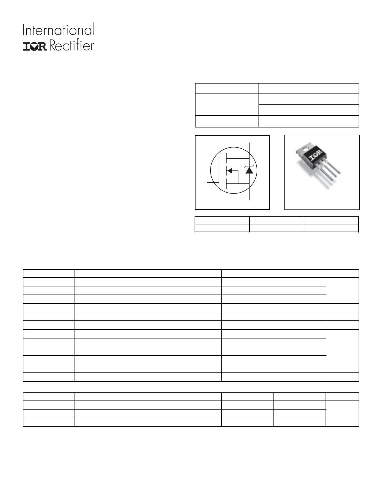
S
D
G
TO-220AB
D
S
D
G
GDS
Gate Drain Source
Benefits
l Low R
DSON
Reduces Losses
l Low Gate Charge Improves the Switching
Performance
l Improved Diode Recovery Improves Switching &
EMI Performance
l 30V Gate Voltage Rating Improves Robustness
l Fully Characterized Avalanche SOA
Applications
l Motion Control Applications
l High Efficiency Synchronous Rectification in SMPS
l Uninterruptible Power Supply
l Hard Switched and High Frequency Circuits
V
DSS
150V
R
DS(on)
typ.
12m
:
max.
15m
:
I
D
85A
Absolute Maximum Ratings
Symbol Parameter Units
I
D
@ T
C
= 25°C Continuous Drain Current, V
GS
@ 10V
A
I
D
@ T
C
= 100°C Continuous Drain Current, V
GS
@ 10V
I
DM
Pulsed Drain Current
d
P
D
@T
C
= 25°C
Maximum Power Dissipation
W
Linear Derating Factor
W/°C
V
GS
Gate-to-Source Voltage
V
E
AS (Thermally limited)
Single Pulse Avalanche Energy
e
mJ
T
J
Operating Junction and
°C
T
STG
Storage Temperature Range
Soldering Temperature, for 10 seconds
(1.6mm from case)
Mounting torque, 6-32 or M3 screw
Thermal Resistance
Parameter Typ. Max. Units
R
θ
JC
Junction-to-Case
g
––– 0.43
R
θ
CS
Case-to-Sink, Flat, Greased Surface 0.50 ––– °C/W
R
θ
JA
Junction-to-Ambient
g
––– 62
350
Max.
85
c
60
330
-55 to + 175
2.3
10lb
x
in (1.1N
x
m)
300
±30
120
PD - 97103B
资源评论


芯脉芯城
- 粉丝: 3
- 资源: 4031


最新资源
- c51_2_2.c
- ASCII American Standard Code for Information Interchange
- 一个chm格式的 SQL 函数手册-SQL语言手册文档
- 计算当前月份的天数和剩余天数
- 基于ARM的指令调度和延迟分支
- 基于Vue和TypeScript的极简聊天应用设计源码 - HasChat
- 基于Vue2全家桶和Zcool数据的图片收集网站设计源码 - cool-picture
- 基于C和C++的二维绘制工具设计源码 - DrawPro
- Object.defineProperty 的 IE 补丁object-defineproperty-ie-master.zip
- 整卷预览.mhtml
资源上传下载、课程学习等过程中有任何疑问或建议,欢迎提出宝贵意见哦~我们会及时处理!
点击此处反馈


