没有合适的资源?快使用搜索试试~ 我知道了~
AIKQ120N75CP2 INFINEON 英飞凌 电子元器件芯片.pdf
需积分: 5 0 下载量 142 浏览量
2023-05-25
17:48:21
上传
评论
收藏 1.42MB PDF 举报
温馨提示
试读
16页
AIKQ120N75CP2 INFINEON 英飞凌 电子元器件芯片
资源推荐
资源详情
资源评论
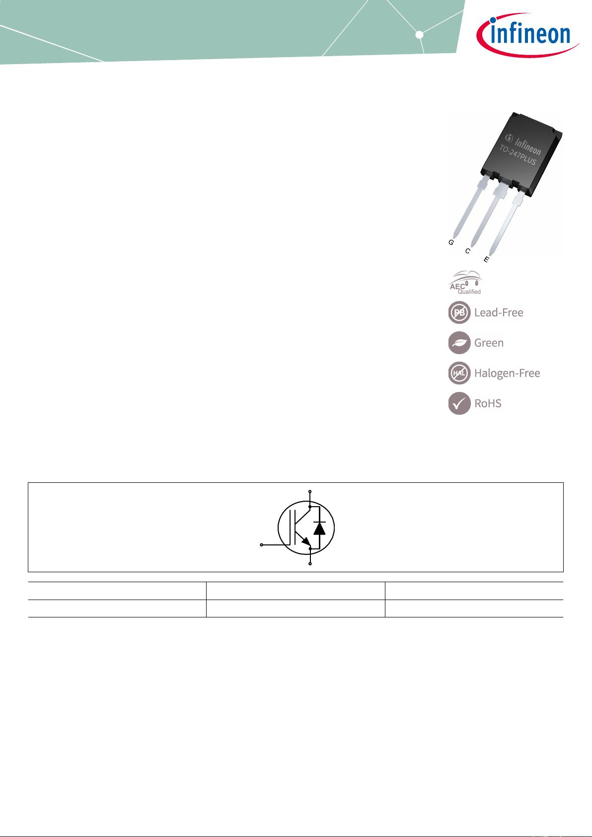
EDT2 IGBT and emitter controlled diode in TO247PLUS package
Features
• V
CE
= 750 V
• I
C
= 120 A
• 750 V collector-emitter blocking voltage capability
• Suitable for 470 V V
DC
systems and increase overvoltage margin for 400 V V
DC
systems
• Very low V
CE(sat)
, 1.30 V at I
Cnom
= 120 A, 25°C
• Short circuit robust t
sc
= 5 µs at V
CE
= 470 V, V
GE
= 15 V
• Self limiting current under short circuit condition
• Positive thermal coeicient and very tight parameter distribution for easy paralleling
• Drop-in replacement for previous generation devices I
C
= 120 A, T
c
= 100°C
• Excellent current sharing in parallel operation
• Smooth switching characteristics, low EMI signature
• Low gate charge Q
G
• Simple gate drive design
• Co-packed with fast so recovery emitter controlled 3 diode
• TO247PLUS package with high creepage distance
• High reliability
Potential applications
• xEV traction inverter
• DC-link discharge switch
• Automotive aux-drives
Product validation
• Qualified for automotive applications
• Qualified according to AEC-Q101
TO-247PLUS – 3Pin
4
2021-10-27 restricted Copyright © Infineon Technologies AG 2021. All rights reserved.
Description
G
C
E
Type Package Marking
AIKQ120N75CP2 PG-TO247PLUS-3 AKQ12FCP
AIKQ120N75CP2
EDT2 IGBT
Datasheet Please read the sections "Important notice" and "Warnings" at the end of this document Revision 1.10
www.infineon.com 2022-03-16
Table of contents
Description . . . . . . . . . . . . . . . . . . . . . . . . . . . . . . . . . . . . . . . . . . . . . . . . . . . . . . . . . . . . . . . . . . . . . . . . . . . . . . . . . . 1
Features . . . . . . . . . . . . . . . . . . . . . . . . . . . . . . . . . . . . . . . . . . . . . . . . . . . . . . . . . . . . . . . . . . . . . . . . . . . . . . . . . . . . .1
Potential applications . . . . . . . . . . . . . . . . . . . . . . . . . . . . . . . . . . . . . . . . . . . . . . . . . . . . . . . . . . . . . . . . . . . . . . . 1
Product validation . . . . . . . . . . . . . . . . . . . . . . . . . . . . . . . . . . . . . . . . . . . . . . . . . . . . . . . . . . . . . . . . . . . . . . . . . . . 1
Table of contents . . . . . . . . . . . . . . . . . . . . . . . . . . . . . . . . . . . . . . . . . . . . . . . . . . . . . . . . . . . . . . . . . . . . . . . . . . . . 2
1 Package . . . . . . . . . . . . . . . . . . . . . . . . . . . . . . . . . . . . . . . . . . . . . . . . . . . . . . . . . . . . . . . . . . . . . . . . . . . . . . . . . . . . . 3
2 IGBT . . . . . . . . . . . . . . . . . . . . . . . . . . . . . . . . . . . . . . . . . . . . . . . . . . . . . . . . . . . . . . . . . . . . . . . . . . . . . . . . . . . . . . . . .3
3 Diode . . . . . . . . . . . . . . . . . . . . . . . . . . . . . . . . . . . . . . . . . . . . . . . . . . . . . . . . . . . . . . . . . . . . . . . . . . . . . . . . . . . . . . . .5
4 Characteristics diagrams . . . . . . . . . . . . . . . . . . . . . . . . . . . . . . . . . . . . . . . . . . . . . . . . . . . . . . . . . . . . . . . . . . . . . 7
5 Package outlines . . . . . . . . . . . . . . . . . . . . . . . . . . . . . . . . . . . . . . . . . . . . . . . . . . . . . . . . . . . . . . . . . . . . . . . . . . . .14
Revision history . . . . . . . . . . . . . . . . . . . . . . . . . . . . . . . . . . . . . . . . . . . . . . . . . . . . . . . . . . . . . . . . . . . . . . . . . . . . 15
Disclaimer . . . . . . . . . . . . . . . . . . . . . . . . . . . . . . . . . . . . . . . . . . . . . . . . . . . . . . . . . . . . . . . . . . . . . . . . . . . . . . . . . .16
AIKQ120N75CP2
EDT2 IGBT
Table of contents
Datasheet 2 Revision 1.10
2022-03-16
1 Package
Table 1 Characteristic values
Parameter Symbol Note or test condition Values Unit
Min. Typ. Max.
Internal emitter
inductance measured 5
mm (0.197 in) from case
L
E
13.0 nH
Storage temperature T
stg
-55 150 °C
Soldering temperature wave soldering 1.6 mm (0.063 in.) from case
for 10 s
260 °C
Thermal resistance,
junction-ambient
R
th(j-a)
40 K/W
2 IGBT
Table 2 Maximum rated values
Parameter Symbol Note or test condition Values Unit
Collector-emitter voltage V
CE
750 V
DC collector current,
limited by T
vjmax
I
C
T
c
= 25 °C 150 A
T
c
= 100 °C 120
Pulsed collector current, t
p
limited by T
vjmax
I
Cpulse
360 A
Turn-o safe operating
area
V
CE
≤ 750 V, t
p
= 1 µs, T
vj
≤ 175 °C 360 A
Gate-emitter voltage V
GE
±20 V
Transient gate-emitter
voltage
V
GE
t
p
<0.1 µs, D<0.01 ±30 V
Short-circuit withstand
time
t
SC
V
CC
≤ 470 V, V
GE
=15 V, Allowed number of
short circuits < 1000, Time between short
circuits ≥ 1.0 s, T
vj
= 25 °C
5 µs
Power dissipation P
tot
T
c
= 25 °C 682 W
T
c
= 100 °C 341
Table 3 Characteristic values
Parameter Symbol Note or test condition Values Unit
Min. Typ. Max.
Collector-emitter
saturation voltage
V
CEsat
I
C
= 120 A, V
GE
=15 V T
vj
= 25 °C 1.3 1.5 V
T
vj
= 175 °C 1.53
Gate-emitter threshold
voltage
V
GEth
I
C
= 1.6 mA, V
CE
= V
GE
, T
vj
=25 °C 5 5.8 6.5 V
(table continues...)
AIKQ120N75CP2
EDT2 IGBT
1 Package
Datasheet 3 Revision 1.10
2022-03-16
Table 3 (continued) Characteristic values
Parameter Symbol Note or test condition Values Unit
Min. Typ. Max.
Zero gate-voltage collector
current
I
CES
V
CE
= 750 V, V
GE
=0 V T
vj
=25 °C 200 µA
T
vj
=175 °C 4000
Gate-emitter leakage
current
I
GES
V
CE
=0 V, V
GE
=20 V 100 nA
Transconductance g
fs
I
C
= 120 A, V
CE
=20 V 90 S
Short-circuit collector
current
I
SC
V
CC
≤ 470 V, V
GE
=15 V, t
SC
≤ 5 µs, Allowed
number of short circuits < 1000 , Time
between short circuits ≥ 1.0 s, T
vj
=25 °C
750 A
Input capacitance C
ies
V
CE
=25 V, V
GE
=0 V, f=100 kHz 13125 pF
Output capacitance C
oes
V
CE
=25 V, V
GE
=0 V, f=100 kHz 337 pF
Reverse transfer
capacitance
C
res
V
CE
=25 V, V
GE
=0 V, f=100 kHz 59 pF
Gate charge Q
G
I
C
= 120 A, V
GE
=15 V, V
CC
= 600 V, V
CE
=600 V 731 nC
Turn-on delay time t
don
V
CE
= 470 V, V
GE
= -8/15 V,
R
Gon
= 5 Ω, R
Go
= 5 Ω,
L
σ
=50 nH, C
σ
=30 pF
T
vj
= 25 °C,
I
C
= 120 A
71 ns
T
vj
= 175 °C,
I
C
= 120 A
50
Rise time (inductive load) t
r
V
CE
= 470 V, V
GE
= -8/15 V,
R
Gon
= 5 Ω, R
Go
= 5 Ω,
L
σ
=50 nH, C
σ
=30 pF
T
vj
= 25 °C,
I
C
= 120 A
69 ns
T
vj
= 175 °C,
I
C
= 120 A
68
Turn-o delay time t
do
V
CE
= 470 V, V
GE
= -8/15 V,
R
Gon
= 5 Ω, R
Go
= 5 Ω,
L
σ
=50 nH, C
σ
=30 pF
T
vj
= 25 °C,
I
C
= 120 A
244 ns
T
vj
= 175 °C,
I
C
= 120 A
226
Fall time (inductive load) t
f
V
CE
= 470 V, V
GE
= -8/15 V,
R
Gon
= 5 Ω, R
Go
= 5 Ω,
L
σ
=50 nH, C
σ
=30 pF
T
vj
= 25 °C,
I
C
= 120 A
50.5 ns
T
vj
= 175 °C,
I
C
= 120 A
67
Turn-on energy
1)
E
on
V
CE
= 470 V, V
GE
= -8/15 V,
R
Gon
= 5 Ω, R
Go
= 5 Ω,
L
σ
=50 nH, C
σ
=30 pF
T
vj
= 25 °C,
I
C
= 120 A
6.82 mJ
T
vj
= 175 °C,
I
C
= 120 A
7.3
Turn-o energy E
o
V
CE
= 470 V, V
GE
= -8/15 V,
R
Gon
= 5 Ω, R
Go
= 5 Ω,
L
σ
=50 nH, C
σ
=30 pF
T
vj
= 25 °C,
I
C
= 120 A
3.8 mJ
T
vj
= 175 °C,
I
C
= 120 A
4.7
(table continues...)
AIKQ120N75CP2
EDT2 IGBT
2 IGBT
Datasheet 4 Revision 1.10
2022-03-16
剩余15页未读,继续阅读
资源评论
芯脉芯城
- 粉丝: 3
- 资源: 4031
上传资源 快速赚钱
- 我的内容管理 展开
- 我的资源 快来上传第一个资源
- 我的收益 登录查看自己的收益
- 我的积分 登录查看自己的积分
- 我的C币 登录后查看C币余额
- 我的收藏
- 我的下载
- 下载帮助
最新资源
- element-icons
- vs图书管理系统框架 winform + c# + sqlserver + 界面美化
- 基于Springboot的学生成绩管理系统-Java项目-毕业设计
- 基于vue+springboot在线考试系统 框架 idea + vscode + html + css + vue + jav
- shell脚本监控docker容器和supervisor 运行情况
- 图书管理系统框架 winform + c# + sqlserver + 界面美化
- 基于react16.7.0 + antd3.11.6 + axios + 0.18.0的基础上搭建的路由框架.zip
- 3333333333333333333
- STM32软件I2C,已验证
- 使用python的turtle画玫瑰实例代码.rar
资源上传下载、课程学习等过程中有任何疑问或建议,欢迎提出宝贵意见哦~我们会及时处理!
点击此处反馈
安全验证
文档复制为VIP权益,开通VIP直接复制
信息提交成功