没有合适的资源?快使用搜索试试~ 我知道了~
TI-AMC1333M10.pdf
需积分: 9 0 下载量 35 浏览量
2022-11-30
12:48:34
上传
评论 4
收藏 2.02MB PDF 举报
温馨提示
试读
36页
TI-AMC1333M10.pdf
资源推荐
资源详情
资源评论
AMC1333M10 具有 10MHz 内部时钟的
±1V 输入、增强型隔离式 Δ-Σ 精密调制器
1 特性
• 线性输入电压范围:±1V
• 高输入阻抗:2.4GΩ(典型值)
• 低直流误差:
– 失调电压误差:±0.5 mV(最大值)
– 温漂±4µV/°C(最大值)
– 增益误差:±0.2%(最大值)
– 增益漂移:±40ppm/°C(最大值)
• 高 CMTI:100kV/µs(最小值)
• 内部 10MHz 时钟发生器
• 高侧电源缺失检测
• 低 EMI:符合 CISPR-11 和 CISPR-25 标准
• 安全相关认证:
– 符合 DIN EN IEC 60747-17 (VDE 0884-17) 标
准的 8000V
PEAK
增强型隔离
– 符合 UL1577 标准且长达 1 分钟的 5700V
RMS
隔离
• 额定的工业级工作温度范围:–40°C 至 +125°C
2 应用
• 电机驱动器
• 变频器
• 保护继电器
• 电源
3 说明
AMC1333M10 是一款精密 Δ-Σ 调制器,此调制器的输
出与输入电路由抗电磁干扰性能极强的隔离层隔开。该
隔离栅经认证可提供高达 8000V
PEAK
的增强型隔离,
符合 DIN EN IEC 60747-17 (VDE 0884-17) 和
UL1577 标准,并且可支持高达 1.5kV
RMS
的工作电
压。该隔离层可将系统中以不同共模电压电平运行的各
器件隔开,防止高电压冲击导致低压侧器件电气损坏或
对操作员造成伤害。
AMC1333M10 具有 ±1V 双极宽输入电压范围和高输
入电阻,因此可直接连接高电压应用中的电阻分压器。
AMC1333M10 的输出位流与内部生成的时钟同步。通
过使用集成式数字滤波器(如 TMS320F2807x 或
TMS320F2837x 微控制器系列中的数字滤波器)来抽
取位流,该器件可在 39kSPS 数据速率下实现 16 位分
辨率和 87dB 的动态范围。
AMC1333M10 采用 8 引脚宽体 SOIC 封装,额定的工
业级工作温度范围为 –40°C 至 +125°C。
器件信息
(1)
器件型号 封装 封装尺寸(标称值)
AMC1333M10 SOIC (8) 5.85mm × 7.50mm
(1) 如需了解所有可用封装,请参阅数据表末尾的可订购产品附
录。
DVDD
Low-side supply
(3.3 V or 5 V)
AMC1333M10
Reinforced Isolation
CLKOUT
DOUT
DGND
AGND
INP
INN
AVDD
High-side supply
(3.3 V or 5 V)
ISO
-ADC MCU
V
AC
+1 V
0 V
–1 V
典型应用
AMC1333M10
ZHCSQM2 – MAY 2022
本文档旨在为方便起见,提供有关 TI 产品中文版本的信息,以确认产品的概要。有关适用的官方英文版本的最新信息,请访问
www.ti.com,其内容始终优先。TI 不保证翻译的准确性和有效性。在实际设计之前,请务必参考最新版本的英文版本。
English Data Sheet: SBASA71
Table of Contents
1 特性................................................................................... 1
2 应用................................................................................... 1
3 说明................................................................................... 1
4 Revision History.............................................................. 2
5 Pin Configuration and Functions...................................3
6 Specifications.................................................................. 4
6.1 Absolute Maximum Ratings........................................ 4
6.2 ESD Ratings............................................................... 4
6.3 Recommended Operating Conditions.........................5
6.4 Thermal Information....................................................6
6.5 Power Ratings.............................................................6
6.6 Insulation Specifications............................................. 7
6.7 Safety-Related Certifications...................................... 8
6.8 Safety Limiting Values.................................................8
6.9 Electrical Characteristics.............................................9
6.10 Switching Characteristics........................................ 11
6.11 Timing Diagrams..................................................... 11
6.12 Insulation Characteristics Curves........................... 12
6.13 Typical Characteristics............................................ 13
7 Detailed Description......................................................17
7.1 Overview................................................................... 17
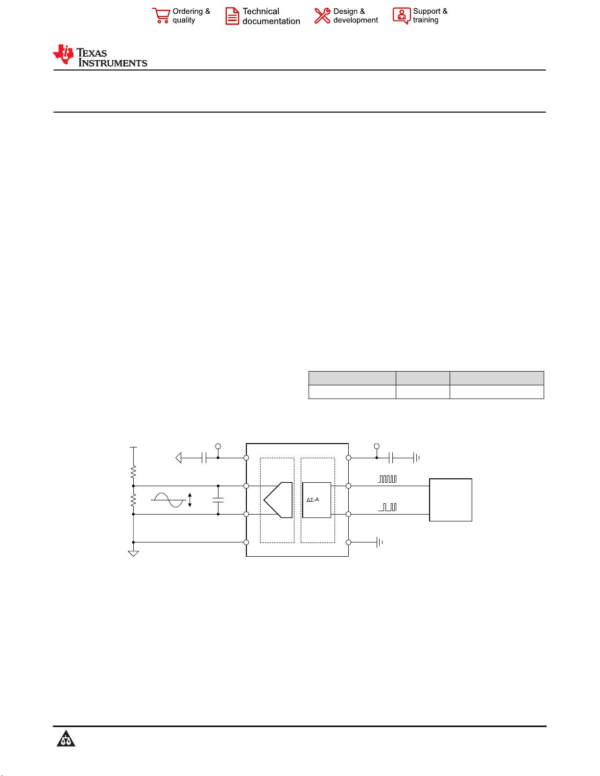
7.2 Functional Block Diagram......................................... 17
7.3 Feature Description...................................................18
7.4 Device Functional Modes..........................................21
8 Application and Implementation.................................. 22
8.1 Application Information............................................. 22
8.2 Typical Application.................................................... 22
8.3 What to Do and What Not to Do............................... 26
9 Power Supply Recommendations................................27
10 Layout...........................................................................28
10.1 Layout Guidelines................................................... 28
10.2 Layout Example...................................................... 28
11 Device and Documentation Support..........................29
11.1 Documentation Support.......................................... 29
11.2 接收文档更新通知................................................... 29
11.3 支持资源..................................................................29
11.4 Trademarks............................................................. 29
11.5 Electrostatic Discharge Caution.............................. 29
11.6 术语表..................................................................... 29
12 Mechanical, Packaging, and Orderable
Information.................................................................... 29
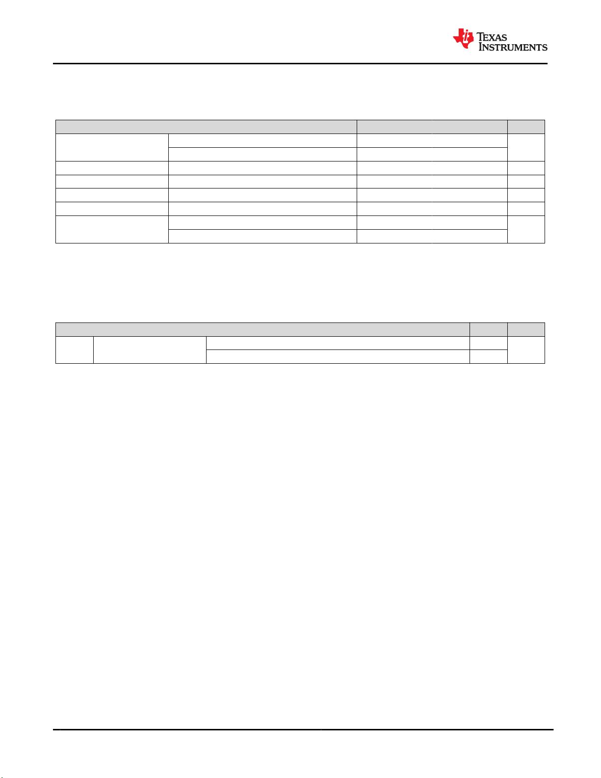
4 Revision History
注:以前版本的页码可能与当前版本的页码不同
DATE REVISION NOTES
May 2022 * Initial release.
AMC1333M10
ZHCSQM2 – MAY 2022
www.ti.com.cn
2 Submit Document Feedback
Copyright © 2022 Texas Instruments Incorporated
Product Folder Links: AMC1333M10
5 Pin Configuration and Functions
AVDD
INP
INN
AGND
DVDD
CLKOUT
DGND
DOUT
1
2
3
4
8
7
6
5
Not to scale
图 5-1. DWV Package, 8-Pin SOIC (Top View)
表 5-1. Pin Functions
PIN
TYPE
DESCRIPTIONNO. NAME
1 AVDD High-side power Analog (high-side) power supply
(1)
2 INP Analog input Noninverting analog input
3 INN Analog input Inverting analog input
4 AGND High-side ground Analog (high-side) ground reference
5 DGND Low-side ground Digital (low-side) ground reference
6 DOUT Digital output Modulator data output
7 CLKOUT Digital output Modulator clock output
8 DVDD Low-side power Digital (low-side) power supply
(1)
(1) See the Power Supply Recommendations section for power-supply decoupling recommendations.
www.ti.com.cn
AMC1333M10
ZHCSQM2 – MAY 2022
Copyright © 2022 Texas Instruments Incorporated
Submit Document Feedback
3
Product Folder Links: AMC1333M10
6 Specifications
6.1 Absolute Maximum Ratings
see
(1)
MIN MAX UNIT
Power-supply voltage
AVDD to AGND –0.3 6.5
V
DVDD to DGND –0.3 6.5
Analog input voltage On the INP and INN pins AGND – 5 AVDD + 0.5 V
Digital input voltage On the CLKIN pin DGND – 0.5 DVDD + 0.5 V
Digital output voltage On the DOUT pin DGND – 0.5 DVDD + 0.5 V
Input current Continuous, any pin except power-supply pins –10 10 mA
Temperature
Junction, T
J
150
°C
Storage, T
stg
–65 150
(1) Operation outside the Absolute Maximum Ratings may cause permanent device damage. Absolute Maximum Ratings do not imply
functional operation of the device at these or any other conditions beyond those listed under Recommended Operating Conditions . If
used outside the Recommended Operating Conditions but within the Absolute Maximum Ratings, the device may not be fully
functional, and this may affect device reliability, functionality, performance, and shorten the device lifetime.
6.2 ESD Ratings
VALUE UNIT
V
(ESD)
Electrostatic discharge
Human-body model (HBM), per ANSI/ESDA/JEDEC JS-001
(1)
±2000
V
Charged-device model (CDM), per per ANSI/ESDA/JEDEC JS-002
(2)
±1000
(1) JEDEC document JEP155 states that 500-V HBM allows safe manufacturing with a standard ESD control process.
(2) JEDEC document JEP157 states that 250-V CDM allows safe manufacturing with a standard ESD control process.
AMC1333M10
ZHCSQM2 – MAY 2022
www.ti.com.cn
4 Submit Document Feedback
Copyright © 2022 Texas Instruments Incorporated
Product Folder Links: AMC1333M10
6.3 Recommended Operating Conditions
over operating ambient temperature range (unless otherwise noted)
MIN NOM MAX UNIT
POWER SUPPLY
AVDD High-side supply voltage AVDD to AGND 3.0 5.0 5.5 V
DVDD Low-side supply voltage DVDD to DGND 2.7 3.3 5.5 V
ANALOG INPUT
V
Clipping
Differential input voltage before clipping output V
IN
= V
INP
– V
INN
±1.25 V
V
FSR
Specified linear differential full-scale voltage V
IN
= V
AINP
– V
AINN
–1 1 V
Absolute common-mode input voltage
(1)
(V
INP
+ V
INN
) / 2 to AGND –2 AVDD V
V
CM
Operating common-mode input voltage
(2)
(V
INP
+ V
INN
) / 2 to AGND,
3.0 V ≤ AVDD < 4.5 V,
|V
INP
– V
INN
| ≤ 1.25 V
–0.8 AVDD – 2.4
V
(V
INP
+ V
INN
) / 2 to AGND,
4.5 V ≤ AVDD ≤ 5.5 V,
|V
INP
– V
INN
| ≤ 1.25 V
–0.8 2.1
TEMPERATURE RANGE
T
A
Specified ambient temperature –40 25 125 °C
(1) Steady-state voltage supported by the device in case of a system failure. See specified common-mode input voltage V
CM
for normal
operation. Observe analog input voltage range as specified in the Absolute Maximum Ratings table.
(2) See the Analog Input section for more details.
www.ti.com.cn
AMC1333M10
ZHCSQM2 – MAY 2022
Copyright © 2022 Texas Instruments Incorporated
Submit Document Feedback
5
Product Folder Links: AMC1333M10
剩余35页未读,继续阅读
资源评论
不觉明了
- 粉丝: 3164
- 资源: 5429
上传资源 快速赚钱
- 我的内容管理 展开
- 我的资源 快来上传第一个资源
- 我的收益 登录查看自己的收益
- 我的积分 登录查看自己的积分
- 我的C币 登录后查看C币余额
- 我的收藏
- 我的下载
- 下载帮助
安全验证
文档复制为VIP权益,开通VIP直接复制
信息提交成功