没有合适的资源?快使用搜索试试~ 我知道了~
资源推荐
资源详情
资源评论
Micron Serial NOR Flash Memory
3V, Multiple I/O, 4KB, 32KB, 64KB, Sector Erase
MT25QL256ABA
Features
• SPI-compatible serial bus interface
• Single and double transfer rate (STR/DTR)
• Clock frequency
– 133 MHz (MAX) for all protocols in STR
– 90 MHz (MAX) for all protocols in DTR
• Dual/quad I/O commands for increased through-
put up to 90 MB/s
• Supported protocols: Extended, Dual and Quad I/O
both STR and DTR
• Execute-in-place (XIP)
• PROGRAM/ERASE SUSPEND operations
• Volatile and nonvolatile configuration settings
• Software reset
• Additional reset pin for selected part numbers
• 3-byte and 4-byte address modes – enable memory
access beyond 128Mb
• Dedicated 64-byte OTP area outside main memory
– Readable and user-lockable
– Permanent lock with PROGRAM OTP command
• Erase capability
– Bulk erase
– Sector erase 64KB uniform granularity
– Subsector erase 4KB, 32KB granularity
• Erase performance: 400KB/sec (64KB sector)
• Erase performance: 80KB/sec (4KB sub-sector)
• Program performance: 2MB/sec
• Security and write protection
– Volatile and nonvolatile locking and software
write protection for each 64KB sector
– Nonvolatile configuration locking
– Password protection
– Hardware write protection: nonvolatile bits
(BP[3:0] and TB) define protected area size
– Program/erase protection during power-up
– CRC detects accidental changes to raw data
• Electronic signature
– JEDEC-standard 3-byte signature (BA19h)
– Extended device ID: two additional bytes identify
device factory options
• JESD47H-compliant
– Minimum 100,000 ERASE cycles per sector
– Data retention: 20 years (TYP)
Options Marking
• Voltage
– 2.7–3.6V L
• Density
– 256Mb 256
• Device stacking
– Monolithic A
• Device generation B
• Die revision A
• Pin configuration
– RESET# and HOLD# 8
• Sector size
– 64KB E
• Packages – JEDEC-standard, RoHS-
compliant
– 24-ball T-PBGA 05/6mm × 8mm
(5 × 5 array)
12
– 24-ball T-PBGA 05/6mm × 8mm
(4 × 6 array)
14
– 16-pin SOP2, 300 mils
(SO16W, SO16-Wide, SOIC-16)
SF
– W-PDFN-8 6mm × 5mm
(MLP8 6mm × 5mm)
W7
– W-PDFN-8 8mm × 6mm
(MLP8 8mm × 6mm)
W9
• Security features
– Standard security 0
• Special options
– Standard S
– Automotive A
• Operating temperature range
– From –40°C to +85°C IT
– From –40°C to +105°C AT
– From –40°C to +125°C UT
256Mb, 3V Multiple I/O Serial Flash Memory
Features
CCMTD-1725822587-3368
mt25q-qljs-L256-ABA-xxT.pdf - Rev. K 07/18 EN
1
Micron Technology, Inc. reserves the right to change products or specifications without notice.
© 2014 Micron Technology, Inc. All rights reserved.
Products and specifications discussed herein are subject to change by Micron without notice.
Part Number Ordering
Micron Serial NOR Flash devices are available in different configurations and densities. Verify valid part numbers
by using Micron’s part catalog search at www.micron.com. To compare features and specifications by device type,
visit www.micron.com/products. Contact the factory for devices not found.
Figure 1: Part Number Ordering Information
Production Status
Blank = Production
ES = Engineering samples
QS = Qualification samples
Operating Temperature
IT = –40°C to +85°C
AT = –40°C to +105°C
UT = –40°C to +125°C
Special Options
S = Standard
A = Automotive grade AEC-Q100
Security Features
0 = Standard default security
Package Codes
12 = 24-ball T-PBGA, 05/6 x 8mm (5 x 5 array)
14 = 24-ball T-PBGA, 05/6 x 8mm (4 x 6 array)
SC = 8-pin SOP2, 150 mils
SE = 8-pin SOP2, 208 mils
SF = 16-pin SOP2, 300 mils
W7 = 8-pin W-PDFN, 6 x 5mm
W9 = 8-pin W-PDFN, 8 x 6mm
5x = WLCSP package
1
Sector size
E = 64KB sectors, 4KB and 32KB subsectors
Micron Technology
Part Family
25Q = SPI NOR
Voltage
L = 2.7–3.6V
U = 1.7–2.0V
Density
064 = 64Mb (8MB)
128 = 128Mb (16MB)
256 = 256Mb (32MB)
512 = 512Mb (64MB)
01G = 1Gb (128MB)
02G = 2Gb (256MB)
Stack
A = 1 die/1 S#
B = 2 die/1 S#
C = 4 die/1 S#
Device Generation
B = 2nd generation
Die Revision
A = Rev. A
B = Rev. B
Pin Configuration Option
1 = HOLD# pin
3 = RESET# pin
8 = RESET# and HOLD# pin
MT 25Q L xxx A BA 1 E SF IT0- S ES
Note:
1. WLCSP package codes, package size, and availability are density-specific. Contact the factory for availability.
256Mb, 3V Multiple I/O Serial Flash Memory
Features
CCMTD-1725822587-3368
mt25q-qljs-L256-ABA-xxT.pdf - Rev. K 07/18 EN
2
Micron Technology, Inc. reserves the right to change products or specifications without notice.
© 2014 Micron Technology, Inc. All rights reserved.
Contents
Important Notes and Warnings ......................................................................................................................... 8
Device Description ........................................................................................................................................... 9
Device Logic Diagram ................................................................................................................................. 10
Advanced Security Protection ..................................................................................................................... 10
Signal Assignments – Package Code: 12 ........................................................................................................... 11
Signal Assignments – Package Code: 14 ........................................................................................................... 12
Signal Assignments – Package Code: SF ........................................................................................................... 13
Signal Assignments – Package Code: W7, W9 .................................................................................................... 14
Signal Descriptions ......................................................................................................................................... 15
Package Dimensions – Package Code: 12 ......................................................................................................... 17
Package Dimensions – Package Code: 14 ......................................................................................................... 18
Package Dimensions – Package Code: SF ......................................................................................................... 19
Package Dimensions – Package Code: W7 ........................................................................................................ 20
Package Dimensions – Package Code: W9 ........................................................................................................ 21
Memory Map – 256Mb Density ....................................................................................................................... 22
Status Register ................................................................................................................................................ 23
Block Protection Settings ............................................................................................................................ 24
Flag Status Register ......................................................................................................................................... 25
Extended Address Register .............................................................................................................................. 26
Internal Configuration Register ....................................................................................................................... 27
Nonvolatile Configuration Register .................................................................................................................. 28
Volatile Configuration Register ........................................................................................................................ 30
Supported Clock Frequencies ..................................................................................................................... 31
Enhanced Volatile Configuration Register ........................................................................................................ 33
Security Registers ........................................................................................................................................... 34
Sector Protection Security Register .................................................................................................................. 35
Nonvolatile and Volatile Sector Lock Bits Security ............................................................................................ 36
Volatile Lock Bit Security Register .................................................................................................................... 36
Device ID Data ............................................................................................................................................... 37
Serial Flash Discovery Parameter Data ............................................................................................................. 38
Command Definitions .................................................................................................................................... 39
Software RESET Operations ............................................................................................................................ 45
RESET ENABLE and RESET MEMORY Commands ....................................................................................... 45
READ ID Operations ....................................................................................................................................... 46
READ ID and MULTIPLE I/O READ ID Commands ...................................................................................... 46
READ SERIAL FLASH DISCOVERY PARAMETER Operation .............................................................................. 47
READ SERIAL FLASH DISCOVERY PARAMETER Command ......................................................................... 47
READ MEMORY Operations ............................................................................................................................ 48
4-BYTE READ MEMORY Operations ................................................................................................................ 49
READ MEMORY Operations Timings ............................................................................................................... 50
WRITE ENABLE/DISABLE Operations ............................................................................................................. 57
READ REGISTER Operations ........................................................................................................................... 58
WRITE REGISTER Operations ......................................................................................................................... 59
CLEAR FLAG STATUS REGISTER Operation ..................................................................................................... 61
PROGRAM Operations .................................................................................................................................... 62
4-BYTE PROGRAM Operations ........................................................................................................................ 63
PROGRAM Operations Timings ....................................................................................................................... 63
ERASE Operations .......................................................................................................................................... 66
SUSPEND/RESUME Operations ..................................................................................................................... 68
PROGRAM/ERASE SUSPEND Operations .................................................................................................... 68
256Mb, 3V Multiple I/O Serial Flash Memory
Features
CCMTD-1725822587-3368
mt25q-qljs-L256-ABA-xxT.pdf - Rev. K 07/18 EN
3
Micron Technology, Inc. reserves the right to change products or specifications without notice.
© 2014 Micron Technology, Inc. All rights reserved.
PROGRAM/ERASE RESUME Operations ...................................................................................................... 68
ONE-TIME PROGRAMMABLE Operations ....................................................................................................... 70
READ OTP ARRAY Command ...................................................................................................................... 70
PROGRAM OTP ARRAY Command .............................................................................................................. 70
ADDRESS MODE Operations .......................................................................................................................... 72
ENTER and EXIT 4-BYTE ADDRESS MODE Command ................................................................................ 72
DEEP POWER-DOWN Operations ................................................................................................................... 72
ENTER DEEP POWER-DOWN Command .................................................................................................... 72
RELEASE FROM DEEP POWER-DOWN Command ....................................................................................... 72
DEEP POWER-DOWN Timings .................................................................................................................... 73
QUAD PROTOCOL Operations ........................................................................................................................ 75
ENTER or RESET QUAD INPUT/OUTPUT MODE Command ....................................................................... 75
CYCLIC REDUNDANCY CHECK Operations .................................................................................................... 76
State Table ..................................................................................................................................................... 78
XIP Mode ....................................................................................................................................................... 79
Activate and Terminate XIP Using Volatile Configuration Register ................................................................. 79
Activate and Terminate XIP Using Nonvolatile Configuration Register .......................................................... 79
Confirmation Bit Settings Required to Activate or Terminate XIP .................................................................. 80
Terminating XIP After a Controller and Memory Reset ................................................................................. 80
Power-Up and Power-Down ............................................................................................................................ 81
Power-Up and Power-Down Requirements .................................................................................................. 81
Active, Standby, and Deep Power-Down Modes ................................................................................................ 83
Power Loss and Interface Rescue ..................................................................................................................... 83
Recovery .................................................................................................................................................... 83
Power Loss Recovery ................................................................................................................................... 84
Interface Rescue ......................................................................................................................................... 84
Initial Delivery Status ..................................................................................................................................... 84
Absolute Ratings and Operating Conditions ..................................................................................................... 85
DC Characteristics and Operating Conditions .................................................................................................. 87
AC Characteristics and Operating Conditions .................................................................................................. 89
AC Reset Specifications ................................................................................................................................... 91
Program/Erase Specifications ......................................................................................................................... 95
Revision History ............................................................................................................................................. 96
Rev. K – 07/18 ............................................................................................................................................. 96
Rev. J – 03/18 .............................................................................................................................................. 96
Rev. I – 07/17 .............................................................................................................................................. 96
Rev. H – 10/16 ............................................................................................................................................. 96
Rev. G – 07/16 ............................................................................................................................................. 96
Rev. F – 06/16 ............................................................................................................................................. 96
Rev. E – 01/16 ............................................................................................................................................. 96
Rev. D – 10/15 ............................................................................................................................................. 96
Rev. C – 9/15 ............................................................................................................................................... 97
Rev. B – 6/15 ............................................................................................................................................... 97
Rev. A – 06/14 ............................................................................................................................................. 97
256Mb, 3V Multiple I/O Serial Flash Memory
Features
CCMTD-1725822587-3368
mt25q-qljs-L256-ABA-xxT.pdf - Rev. K 07/18 EN
4
Micron Technology, Inc. reserves the right to change products or specifications without notice.
© 2014 Micron Technology, Inc. All rights reserved.
List of Figures
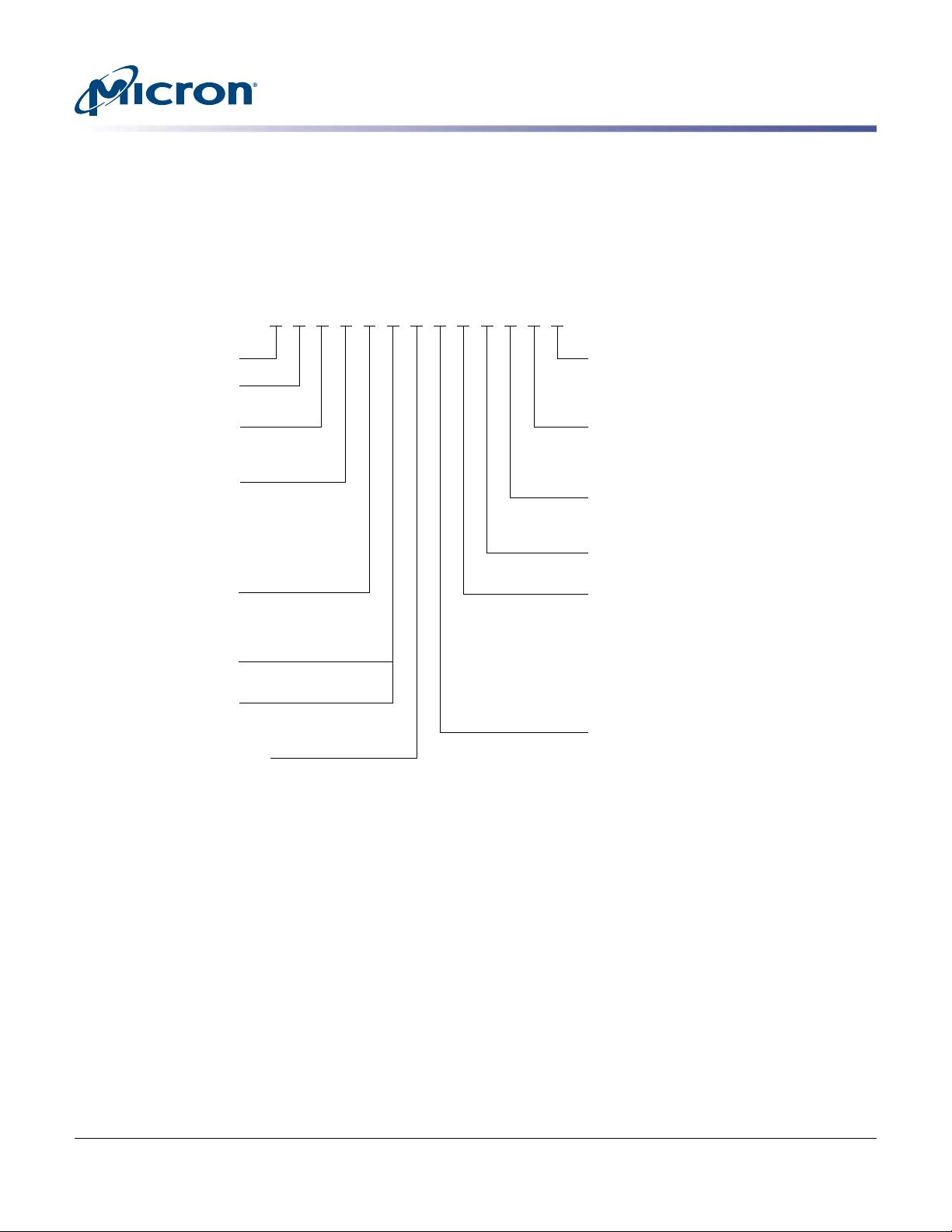
Figure 1: Part Number Ordering Information .................................................................................................... 2
Figure 2: Block Diagram .................................................................................................................................. 9
Figure 3: Logic Diagram ................................................................................................................................. 10
Figure 4: 24-Ball T-BGA, 5 x 5 (Balls Down) ..................................................................................................... 11
Figure 5: 24-Ball TBGA, 4 x 6 (Balls Down) ...................................................................................................... 12
Figure 6: 16-Pin, Plastic Small Outline – SO16 (Top View) ................................................................................ 13
Figure 7: 8-Pin, SOP2 or W-PDFN (Top View) ................................................................................................. 14
Figure 8: 24-Ball T-PBGA (5 x 5 ball grid array) – 6mm x 8mm .......................................................................... 17
Figure 9: 24-Ball T-PBGA (24b05) – 6mm x 8mm ............................................................................................. 18
Figure 10: 16-Pin SOP2 – 300 Mils Body Width ................................................................................................ 19
Figure 11: W-PDFN-8 (MLP8) – 6mm x 5mm .................................................................................................. 20
Figure 12: W-PDFN-8 (MLP8) – 8mm x 6mm .................................................................................................. 21
Figure 13: Memory Array Segments ................................................................................................................ 26
Figure 14: Internal Configuration Register ...................................................................................................... 27
Figure 15: Sector and Password Protection ..................................................................................................... 34
Figure 16: RESET ENABLE and RESET MEMORY Command ........................................................................... 45
Figure 17: READ ID and MULTIPLE I/O READ ID Commands ......................................................................... 46
Figure 18: READ SERIAL FLASH DISCOVERY PARAMETER Command – 5Ah ................................................... 47
Figure 19: READ – 03h/13h
3
........................................................................................................................... 50
Figure 20: FAST READ – 0Bh/0Ch
3
................................................................................................................. 50
Figure 21: DUAL OUTPUT FAST READ – 3Bh/3Ch
3
......................................................................................... 51
Figure 22: DUAL INPUT/OUTPUT FAST READ – BBh/BCh
3
............................................................................ 51
Figure 23: QUAD OUTPUT FAST READ – 6Bh/6Ch
3
........................................................................................ 52
Figure 24: QUAD INPUT/OUTPUT FAST READ – EBh/ECh
3
............................................................................ 52
Figure 25: QUAD INPUT/OUTPUT WORD READ – E7h
3
................................................................................. 53
Figure 26: DTR FAST READ – 0Dh/0Eh
3
.......................................................................................................... 54
Figure 27: DTR DUAL OUTPUT FAST READ – 3Dh
3
........................................................................................ 54
Figure 28: DTR DUAL INPUT/OUTPUT FAST READ – BDh
3
............................................................................ 55
Figure 29: DTR QUAD OUTPUT FAST READ – 6Dh
3
........................................................................................ 56
Figure 30: DTR QUAD INPUT/OUTPUT FAST READ – EDh
3
............................................................................ 56
Figure 31: WRITE ENABLE and WRITE DISABLE Timing ................................................................................. 57
Figure 32: READ REGISTER Timing ................................................................................................................ 58
Figure 33: WRITE REGISTER Timing .............................................................................................................. 60
Figure 34: CLEAR FLAG STATUS REGISTER Timing ........................................................................................ 61
Figure 35: PAGE PROGRAM Command .......................................................................................................... 63
Figure 36: DUAL INPUT FAST PROGRAM Command ...................................................................................... 64
Figure 37: EXTENDED DUAL INPUT FAST PROGRAM Command ................................................................... 64
Figure 38: QUAD INPUT FAST PROGRAM Command ..................................................................................... 65
Figure 39: EXTENDED QUAD INPUT FAST PROGRAM Command ................................................................... 65
Figure 40: SUBSECTOR and SECTOR ERASE Timing ....................................................................................... 67
Figure 41: BULK ERASE Timing ...................................................................................................................... 67
Figure 42: PROGRAM/ERASE SUSPEND and RESUME Timing ........................................................................ 69
Figure 43: READ OTP ARRAY Command Timing ............................................................................................. 70
Figure 44: PROGRAM OTP Command Timing ................................................................................................. 71
Figure 45: ENTER DEEP POWER-DOWN Timing ............................................................................................. 73
Figure 46: RELEASE FROM DEEP POWER-DOWN Timing ............................................................................... 74
Figure 47: XIP Mode Directly After Power-On .................................................................................................. 79
Figure 48: Power-Up Timing .......................................................................................................................... 82
Figure 49: AC Timing Input/Output Reference Levels ...................................................................................... 86
Figure 50: Reset AC Timing During PROGRAM and ERASE Cycle ..................................................................... 92
256Mb, 3V Multiple I/O Serial Flash Memory
Features
CCMTD-1725822587-3368
mt25q-qljs-L256-ABA-xxT.pdf - Rev. K 07/18 EN
5
Micron Technology, Inc. reserves the right to change products or specifications without notice.
© 2014 Micron Technology, Inc. All rights reserved.
剩余96页未读,继续阅读
资源评论
Tursun225
- 粉丝: 47
- 资源: 2
上传资源 快速赚钱
- 我的内容管理 展开
- 我的资源 快来上传第一个资源
- 我的收益 登录查看自己的收益
- 我的积分 登录查看自己的积分
- 我的C币 登录后查看C币余额
- 我的收藏
- 我的下载
- 下载帮助
安全验证
文档复制为VIP权益,开通VIP直接复制
信息提交成功