


0
Driver
Vdc
Vdc Sense
Line
Voltage
Sense
Neutral
Voltage
Sense
SiC MOSFET
(High Frequency)
Si/SiC (Low
Frequency)
Power Grid
V_N
Ineu
Vdc Sense
F28004x
C2000
TM
MCU
V_L
UCC28700-Q1
TLV71333-Q1
Vdc
5 V
3.3 V
F28004x Control Card
F28004x Control Card
SN6501-Q1
G8
Ic
Ib
Ia
Ineu
Ic
Ib
Ia
15 V & -4 V
15 V & -4 V
15 V & -4 V
G1
G2
G3
G4
G5
G6
PFC Vout
Hall
Sensor
Hall Sensor
x 3
La
Lb
Lc
ISO7721-Q
Fault
Reset
5 V
G7
15 V & -4 V
UCC21520-Q1
4 × TIDA-01605
G1 G2 G3 G4 G5 G6 G7 G8
1
ZHCU459A–March 2018–Revised August 2018
TIDUE54 — http://www-s.ti.com/sc/techlit/TIDUE54
版权 © 2018, Texas Instruments Incorporated
效率为
98.6%
且适用于
HEV/EV
车载充电器的
6.6kW
图腾柱
PFC
参考设计
TI Designs
::
TIDA-01604
效效率率为为
98.6%
且且适适用用于于
HEV/EV
车车载载充充电电器器的的
6.6kW
图图腾腾柱柱
PFC
参参考考设设计计
说说明明
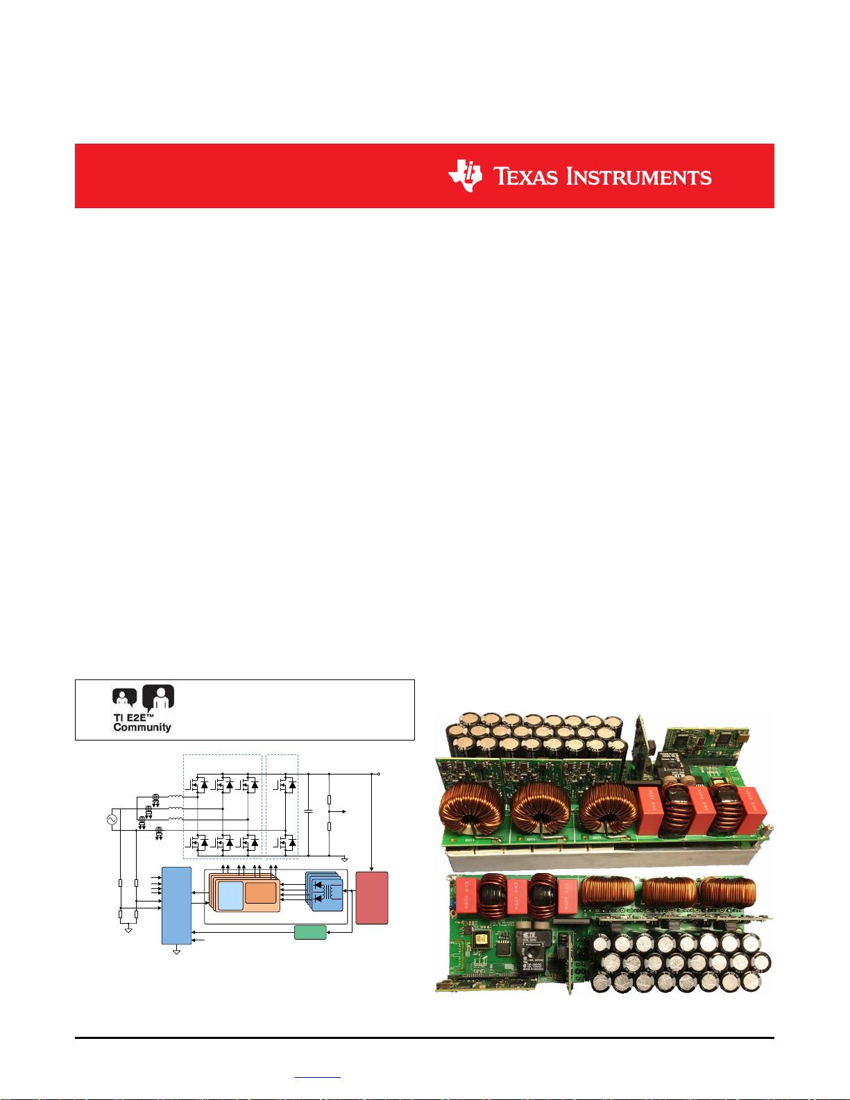
此参考设计介绍了适用于车载充电器的 6.6kW 图腾柱
(TTPL) 无桥功率因数校正 (PFC) 解决方案。功率级由
C2000™微控制器 (MCU) 通过 SiC 隔离式栅极驱动器
实现碳化硅 (SiC) MOSFET 的驱动。此设计采用了三相
交错技术并在连续导通模式 (CCM) 中运行,在 240V 输
入电压和 6.6kW 全功率下可实现 98.60% 的效率。
C2000 控制器可实现切相和自适应死区时间控制,从而
改善轻载条件下的功率因数。栅极驱动器板(参见
TIDA-01605)实现了增强型隔离,可承受超过 100V/ns
的共模瞬态抗扰度 (CMTI)。栅极驱动器板还包含两级关
断电路,可在短路情况下保护 MOSFET 抵御电压过
冲。
资资源源
TIDA-01604 设计文件夹
UCC21520-Q1 产品文件夹
TMS320F280049 产品文件夹
UCC28700-Q1 产品文件夹
TL1963A-Q1 产品文件夹
ISO7731-Q1 产品文件夹
C2000WARE-
DIGITALPOWER-SDK
工具文件夹
咨询我们的 E2E™ 专家
特特性性
• 高功率密度、高效率 PFC 设计,可为高达 6.6kW
的系统供电
• SiC MOSFET 具有 TI 驱动器,能够为客户提供更高
的集成度
• 具有增强型隔离和两级关断保护功能的半桥型和紧
凑型隔离式栅极驱动器
• 完全数字化控制,通过高性能 C2000™ 控制器实现
先进的控制方案
• 峰值效率为 98.86%,功率因素大于 0.99,且总谐波
失真 (THD) 小于 2%
• 三相交错运行方式,具有切相控制功能
• 400V 至 600V 的可编程输出电压
应应用用
• HEV/EV 牵引逆变器
• HEV/EV 车载充电器
• 电子控制单元
• HEV/EV 直流/直流转换器

剩余76页未读,继续阅读
资源评论

- #完美解决问题
- #运行顺畅
- #内容详尽
- #全网独家
- #注释完整
 吉利吉利2023-07-24对于初学者来说,这份指南易于理解,语言简洁明了,能够帮助他们快速入门车载充电器设计领域。
 月小烟2023-07-24这份指南提供了详实而实用的信息,对于设计车载充电器的人来说是一份不可多得的参考。
 精准小天使2023-07-24该文件全面介绍了TI 6.6kw车载充电器的设计方案,让人能够深入了解其中的技术细节。
 王元祺2023-07-24指南中的案例分析和示意图非常实用,能够帮助读者更好地理解和应用相关知识。
 永远的122023-07-24这份文件对于解决实际问题提供了有价值的建议和指导,减少了设计者在实践中遇到的困惑和错误。

起名真TM的难
- 粉丝: 0
- 资源: 4


最新资源
- 重磅推荐-2024全新Langchain大模型AI应用与多智能体实战开发(视频教程+源码+课件).zip
- 线性时变模型预测控制LTV-MPC在Matlab+Simulink环境下的应用与仿真研究(2020b版),基于Matlab/Simulink的线性时变模型预测控制(LTV-MPC)仿真研究(2020
- "《基于Matlab+YALMIP+Gurobi的配电网两阶段鲁棒故障恢复策略复现与实践》-中科院一区期刊IEEE Transactions on Power Systems中的顶刊成果详解与实现"
- 代码项目文档:早报信息生成与推送系统
- "低速永磁同步电机转子偏心对运行特性及振动噪声影响的研究","转子偏心对低速永磁同步电机性能影响的研究:从齿槽转矩到振动噪声的全面分析",转子偏心对低速永磁同步电机运行特性影响的研究 低速直驱永磁同步
- RTCA DO-311A-2017可充电锂电池和电池系统的最低运行性能标准
- 华为项目管理10大模板(可直接套用)
- 基于大蔗鼠优化策略:改进的大蔗鼠优化算法IGCRA与自然觅食行为结合的元启发式算法研究,改进的IGCRA:三大策略驱动的大蔗鼠优化算法(Greater Cane Rat Algorithm with
- Java期末作业基于javafx实现的任务管理软件源代码+数据库
- 1_base.apk.1
- 界面 多语言动态 切换显示;使用Language.ini进行语言配置; 建立Language-CN.ini,Language-EN.ini对照表,切换内容包括:菜单及控件,文中提示信息等
- 华为ICT大赛2023-2024全国总决赛网络赛道实验试题
- 基于MATLAB的变压器剩磁计算程序:计算输出磁通波形与剩磁值,MATLAB程序在计算变压器剩磁时的输出波形及其计算结果的应用分析,MATLAB程序 变压器剩磁计算 输出磁通波形 计算剩磁值 ,MAT
- CNN-LSSVM卷积神经网络最小二乘支持向量机多变量多步预测,光伏功率预测(Matlab完整源码和数据)
- C语言开发-销售预测项目案例分享
- 微信小程序餐厅扫码点餐项目源码
资源上传下载、课程学习等过程中有任何疑问或建议,欢迎提出宝贵意见哦~我们会及时处理!
点击此处反馈