


JEDEC
STANDARD
Wire Bond Shear Test Method
JESD22-B116B
(Revision of JESD22-B116A, August 2009)
APRIL 2017
JEDEC SOLID STATE TECHNOLOGY ASSOCIATION

NOTICE
JEDEC standards and publications contain material that has been prepared, reviewed, and
approved through the JEDEC Board of Directors level and subsequently reviewed and approved
by the JEDEC legal counsel.
JEDEC standards and publications are designed to serve the public interest through eliminating
misunderstandings between manufacturers and purchasers, facilitating interchangeability and
improvement of products, and assisting the purchaser in selecting and obtaining with minimum
delay the proper product for use by those other than JEDEC members, whether the standard is to
be used either domestically or internationally.
JEDEC standards and publications are adopted without regard to whether or not their adoption
may involve patents or articles, materials, or processes. By such action JEDEC does not assume
any liability to any patent owner, nor does it assume any obligation whatever to parties adopting
the JEDEC standards or publications.
The information included in JEDEC standards and publications represents a sound approach to
product specification and application, principally from the solid state device manufacturer
viewpoint. Within the JEDEC organization there are procedures whereby a JEDEC standard or
publication may be further processed and ultimately become an ANSI standard.
No claims to be in conformance with this standard may be made unless all requirements stated in
the standard are met.
Inquiries, comments, and suggestions relative to the content of this JEDEC standard or
publication should be addressed to JEDEC at the address below, or refer to www.jedec.org under
Standards and Documents for alternative contact information.
Published by
©JEDEC Solid State Technology Association 2017
3103 North 10th Street
Suite 240 South
Arlington, VA 22201-2107
This document may be downloaded free of charge; however JEDEC retains the
copyright on this material. By downloading this file the individual agrees not to
charge for or resell the resulting material.
PRICE: Contact JEDEC
Printed in the U.S.A.
All rights reserved

JEDEC Standards No. 22-B116B
Page 1
Test Method B116B
Revision of Test Method B116A
TEST METHOD B116B
WIRE BOND SHEAR TEST
(From JEDEC Board Ballot JCB-17-10, formulated under the cognizance of the JC-14.1 Subcommittee
on Reliability Test Methods for Packaged Devices.)
1 Scope
This test provides a means for determining the strength of a ball bond to a die or package bonding surface,
and may be performed on pre-encapsulation or post-encapsulation devices. This measure of bond strength
is extremely important in determining two features:
1) the integrity of the metallurgical bond which has been formed, and
2) the quality of ball bonds to die or package bonding surfaces.
This test method covers thermosonic (ball) bonds made with small diameter wire from 15 µm to 76 µm
(0.6 mil to 3.0 mil).
This test method can only be used when the bonds are large enough to allow for proper contact with the
shear test chisel and when there are no adjacent interfering structures that would hinder the movement of the
chisel. For consistent shear results the ball height must be at least 4.0 µm (0.16 mils) for ball bonds, which
is the current state of the art for bond shear test equipment at the time of this revision.
This test method can also be used on ball bonds that have had their wire removed and on to which a 2
nd
bond
wire (typically a stitch bond) is placed. This may be known as “stitch on ball” and “reverse bonding”. See
Annex A for additional information.
The wire bond shear test is destructive. It is appropriate for use in process development, process control,
and/or quality assurance.
This test method may be used on ultrasonic (wedge) bonds, however its use has not been shown to be a
consistent indicator of bond integrity. See Annex B for information on performing shear testing on wedge
bonds.
JEDEC Standards No. 22-B116B
Page 2
Test Method B116B
Revision of Test Method B116A
2 Terms and definitions
For the purposes of this standard, the following terms and definitions apply:
2.1 ball bond: The adhesion or welding of a small diameter wire, typically gold or copper, to a
bonding surface metallization, usually an aluminum alloy, using a thermosonic wire bond process.
NOTE 1 The ball bond includes the enlarged spherical, or nail-head, portion of the wire (provided by the flame-off
and first bonding operation), the underlying bonding surface and the ball bond-bonding surface metallurgical weld
interface.
NOTE 2 Gold wire implies a gold alloy in which the gold content is likely 99% or greater. Copper wire implies a
copper alloy of similarly high copper content and also includes copper wire with a very thin coating of palladium.
NOTE 3 At the time of this revision, other wire materials and wire coatings are being evaluated, but there is not
enough information collected to confirm that the fail modes listed in this test method are valid for any of the new wire
types.
2.2 bonding surface: Either 1) the die pad metallization or 2) the package surface metallization to
which the wire is ball bonded.
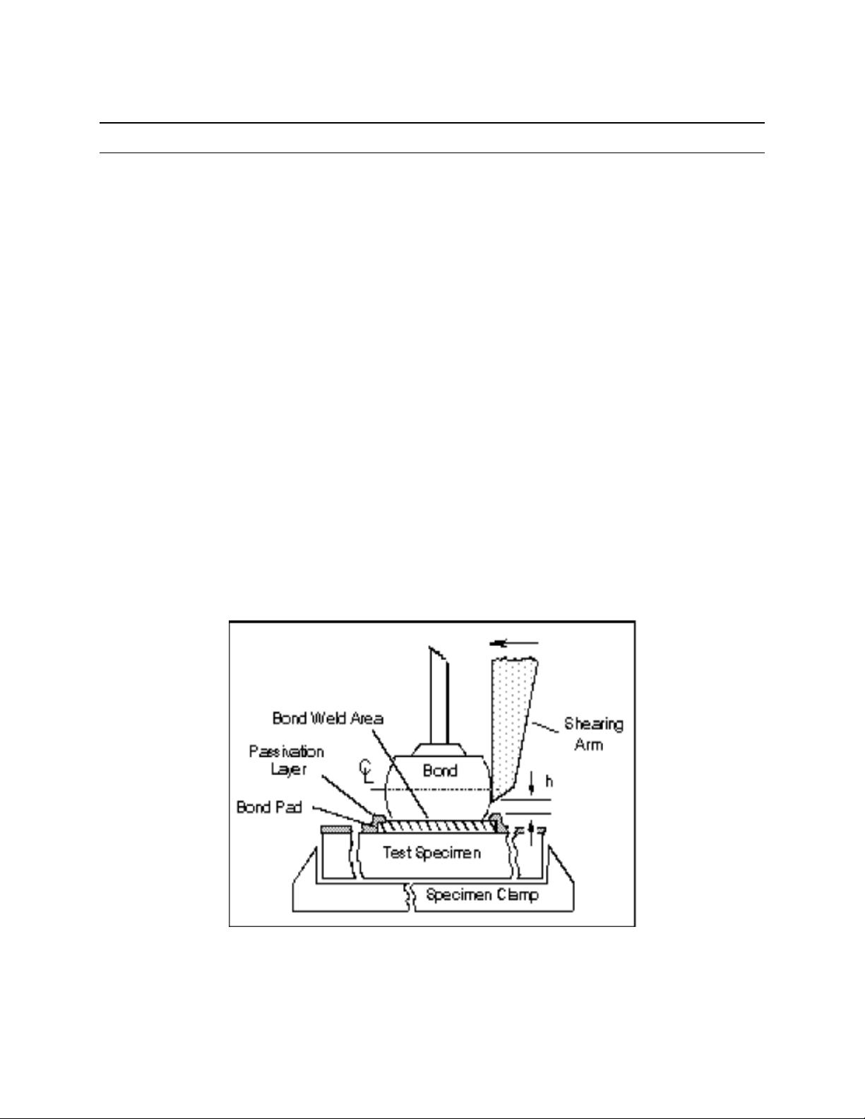
2. bond shear: A process in which an instrument uses a chisel-shaped tool to shear or push a ball
bond off the bonding surface (see Figure 1).
NOTE The force required to cause this separation is recorded and is referred to as the bond shear force. The bond
shear force of a ball bond, when correlated to the diameter of the ball bond, is an indicator of the quality of the
metallurgical bond between the ball bond and the bonding surface metallization.
Figure 1 — Bond shear set-up for bond on die bonding pad
(Similar setup for bonds on other bonding surfaces, such as package substrate/leadframe)

JEDEC Standards No. 22-B116B
Page 3
Test Method B116B
Revision of Test Method B116A
2 Terms and definitions (cont’d)
2.4 shear tool; shear arm: A chisel (made of tungsten carbide or an equivalent material with similar
mechanical properties) with specific angles on the bottom and back of the tool to ensure a shearing action.
2.5 stitch bond: The second bond during the ball (thermosonic) bonding process, in which the wire is
typically bonded to the package bonding surface.
NOTE 1 A stitch bond may also be referred to as a crescent bond.
NOTE 2 For some unique constructions (e.g., “stitch on ball”), the second bond may be formed on top of another ball
bond, from which the wire has been removed.
2.6 wedge bond: The adhesion or weld of a thin wire, typically aluminum, copper, or gold to a die pad
metallization or the package bonding surface, usually a plated leadframe post or finger, using an ultrasonic
wire bonding process.
NOTE See Annex B for information on performing shear testing on wedge bonds.
3 Apparatus and material
The apparatus and materials required for bond shear shall be as follows:
3.1 Inspection equipment
An optical microscope system or scanning electron microscope providing a minimum of 70X magnification.
A higher magnification may be necessary for 15 µm (0.6 mil) diameter wire.
3.2 Measurement equipment
An optical microscope/measurement system capable of measuring the bond diameter to within ± 2.54 µm
(0.10 mil).
3.3 Workholder
Fixture used to hold the part being tested parallel to the shearing plane and perpendicular to the shear tool.
The fixture shall also eliminate part movement during bond shear testing. If using a caliper controlled
workholder, place the holder so that the shear motion is against the positive stop of the caliper. This is to
ensure that the recoil movement of the caliper controlled workholder does not influence the bond shear test.


