介电屏蔽边界条件用于静电场建模仿真
版权申诉
73 浏览量
2022-06-07
20:16:55
上传
评论
收藏 1.06MB PDF 举报

2 | DIELECTRIC SHIELDING COMPARISON
Introduction
The dielectric shielding boundary condition is meant to approximate a thin layer of
material with high relative permittivity compared to its surroundings. This boundary
condition is available for electrostatic field modeling. This example compares the dielectric
shielding boundary condition to a full-fidelity model and discusses the range of
applicability of this boundary condition.
ε
r
= 20
ε
r
= 1
V
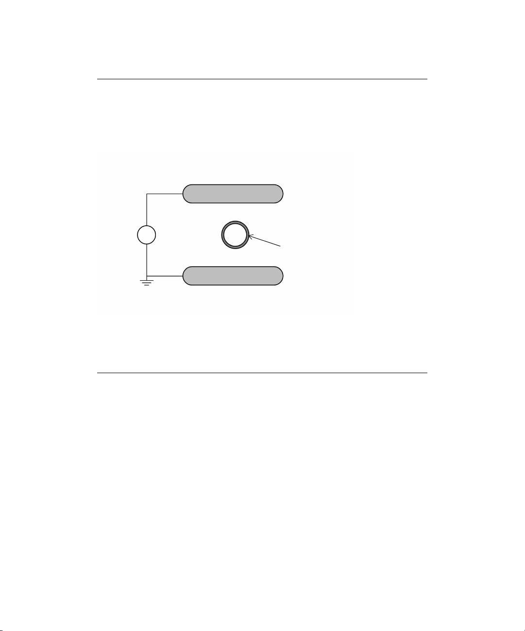
Figure 1: A two-dimensional parallel plate capacitor in free space. A thin-walled circular
inclusion between the plates distorts the electric field.
Model Definition
The situation being modeled is shown in Figure 1. Two parallel plates in free space
(relative permittivity, ε
r
= 1) have a voltage difference applied to them, forming a capacitor.
Between these plates there is a 1 cm outer diameter circular inclusion with a wall thickness
of 1mm. The walls are made of a high dielectric (ε
r
= 20) material.
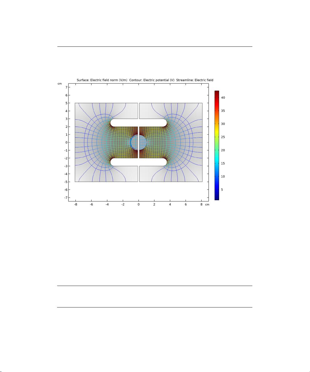
The walls of this inclusion are modeled two ways, first using a full fidelity model that
includes
the thickness of the walls, and also using the dielectric shielding boundary
condition. The inside of the inclusion has the same properties as free space. The two
models are separate, but are being modeled simultaneously for comparison.
The location of the dielectric shielding condition is at the centerline, midway between the
inner an
d outer radii of the full fidelity model. Note that, when using the dielectric
shielding condition, the total volume of the surrounding material is slightly larger, since
the thickness of the wall is not being explicitly modeled.
剩余16页未读,继续阅读

CAE工作者
- 粉丝: 181
- 资源: 1857

下载权益

C知道特权

VIP文章

课程特权
开通VIP


相关推荐
资源上传下载、课程学习等过程中有任何疑问或建议,欢迎提出宝贵意见哦~我们会及时处理!
点击此处反馈


评论0
最新资源