没有合适的资源?快使用搜索试试~ 我知道了~
IMC101T-T038 英飞凌芯片 INFINEON 中文版规格书手册.pdf
需积分: 5 0 下载量 92 浏览量
2023-07-17
09:46:12
上传
评论
收藏 1.11MB PDF 举报
温馨提示
试读
51页
IMC101T-T038 英飞凌芯片 INFINEON 中文版规格书手册
资源推荐
资源详情
资源评论
iMOTION
™
IMC100
High performance motor control IC series
IMC100
Quality Requirement Category: Industry
Feature list
• Motion Control Engine (MCE) as ready-to-use solution for variable speed drives
• Field oriented control (FOC) for permanent magnet synchronous motor (PMSM)
• Space vector PWM with sinusoidal commutation and integrated protection features
• Current sensing via single or leg shunt
• Sensorless operation
• Optional support for hall sensors (analog or digital)
• Optional boost or totem pole PFC control integrated
• Flexible host interface options for motor control commands: UART, PWM or analog input signal
• Support for IEC/UL 60335 (‘Class B’)
• Integrated scripting engine for application flexibility
• Multiple package options
Applications
• Refrigerators
• Home appliances
• Pumps, fans
• ...any other PMSM drive
Ordering Information
Product Type Application Package
IMC099T-T038 single motor, no scripting, no class B TSSOP-38
IMC101T-T038 single motor TSSOP-38
IMC101T-Q048 QFN-48
IMC101T-F048 LQFP-48
IMC101T-F064 LQFP-64
IMC102T-F048 single motor + PFC (boost, totem pole) LQFP-48
IMC102T-F064 LQFP-64
Note: Variants in LQFP-48 package under development.
IMC099T/IMC101T/IMC102T
Datasheet
Please read the Important Notice and Warnings at the end of this document 1.3
www.infineon.com 2019-02-14
Description
iMOTION
™
IMC100 is a family of highly integrated ICs for the control of variable speed drives. By integrating both
the required hardware and soware to perform control of a permanent magnet synchronous motor (PMSM)
they provide the shortest time to market for any motor system at the lowest system and development cost.
The integrated script engine allows to add application flexibility without interfering with the motor and PFC
control algorithm.
M
3-Phase
Inverter
Current Sensing
single / leg shunt
Gate Driver
Power
Supply
Power Factor
Correction
boost/ totem pole
iMOTION™
IMC100
Position
Position Sensing
sensorless / hall
Status LED
Temp Sense
UART
analog
iMOTION
™
IMC100
High performance motor control IC series
Description
Datasheet 2 1.3
2019-02-14
Table of contents
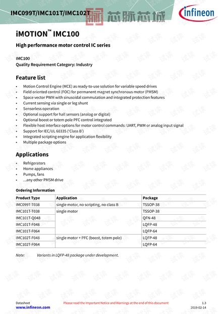
Feature list . . . . . . . . . . . . . . . . . . . . . . . . . . . . . . . . . . . . . . . . . . . . . . . . . . . . . . . . . . . . . . . . . . . . . . . . . . . . . 1
Applications . . . . . . . . . . . . . . . . . . . . . . . . . . . . . . . . . . . . . . . . . . . . . . . . . . . . . . . . . . . . . . . . . . . . . . . . . . . .1
Description . . . . . . . . . . . . . . . . . . . . . . . . . . . . . . . . . . . . . . . . . . . . . . . . . . . . . . . . . . . . . . . . . . . . . . . . . . . . .2
Table of contents . . . . . . . . . . . . . . . . . . . . . . . . . . . . . . . . . . . . . . . . . . . . . . . . . . . . . . . . . . . . . . . . . . . . . . . 3
About this document . . . . . . . . . . . . . . . . . . . . . . . . . . . . . . . . . . . . . . . . . . . . . . . . . . . . . . . . . . . . . . . . . . . 4
1 Block Diagram Reference . . . . . . . . . . . . . . . . . . . . . . . . . . . . . . . . . . . . . . . . . . . . . . . . . . . . . . . . . . . . . . . 5
2 Pin Configuration . . . . . . . . . . . . . . . . . . . . . . . . . . . . . . . . . . . . . . . . . . . . . . . . . . . . . . . . . . . . . . . . . . . . . . .6
2.1 Pin Configuration IMC099T/ IMC101T . . . . . . . . . . . . . . . . . . . . . . . . . . . . . . . . . . . . . . . . . . . . . . . . . . . . . . 6
2.2 Pin Configuration Drawing IMC099T/ IMC101T . . . . . . . . . . . . . . . . . . . . . . . . . . . . . . . . . . . . . . . . . . . . . . 9
2.3 Pin Configuration IMC102T . . . . . . . . . . . . . . . . . . . . . . . . . . . . . . . . . . . . . . . . . . . . . . . . . . . . . . . . . . . . . . 12
2.4 Pin Configuration Drawing IMC102T . . . . . . . . . . . . . . . . . . . . . . . . . . . . . . . . . . . . . . . . . . . . . . . . . . . . . . 15
3 Functional description . . . . . . . . . . . . . . . . . . . . . . . . . . . . . . . . . . . . . . . . . . . . . . . . . . . . . . . . . . . . . . . . .16
3.1 Application schematic motor control single shunt . . . . . . . . . . . . . . . . . . . . . . . . . . . . . . . . . . . . . . . . . 17
3.2 Application schematic motor control leg shunt . . . . . . . . . . . . . . . . . . . . . . . . . . . . . . . . . . . . . . . . . . . . 18
3.3 Application schematic motor control plus boost PFC . . . . . . . . . . . . . . . . . . . . . . . . . . . . . . . . . . . . . . .19
3.4 Application schematic motor control plus totem pole PFC . . . . . . . . . . . . . . . . . . . . . . . . . . . . . . . . . . 20
4 Electrical characteristics and parameters . . . . . . . . . . . . . . . . . . . . . . . . . . . . . . . . . . . . . . . . . . . . . . . 21
4.1 General Parameters . . . . . . . . . . . . . . . . . . . . . . . . . . . . . . . . . . . . . . . . . . . . . . . . . . . . . . . . . . . . . . . . . . . . .21
4.1.1 Parameter Interpretation . . . . . . . . . . . . . . . . . . . . . . . . . . . . . . . . . . . . . . . . . . . . . . . . . . . . . . . . . . . . . . 21
4.1.2 Absolute Maximum Ratings . . . . . . . . . . . . . . . . . . . . . . . . . . . . . . . . . . . . . . . . . . . . . . . . . . . . . . . . . . . . 21
4.1.3 Pin Reliability in Overload . . . . . . . . . . . . . . . . . . . . . . . . . . . . . . . . . . . . . . . . . . . . . . . . . . . . . . . . . . . . . 22
4.1.4 Operating Conditions . . . . . . . . . . . . . . . . . . . . . . . . . . . . . . . . . . . . . . . . . . . . . . . . . . . . . . . . . . . . . . . . . 24
4.2 DC Parameters . . . . . . . . . . . . . . . . . . . . . . . . . . . . . . . . . . . . . . . . . . . . . . . . . . . . . . . . . . . . . . . . . . . . . . . . . 25
4.2.1 Input/Output Characteristics . . . . . . . . . . . . . . . . . . . . . . . . . . . . . . . . . . . . . . . . . . . . . . . . . . . . . . . . . . 25
4.2.2 Analog to Digital Converter (ADC) . . . . . . . . . . . . . . . . . . . . . . . . . . . . . . . . . . . . . . . . . . . . . . . . . . . . . . .27
4.2.3 Power Supply Current . . . . . . . . . . . . . . . . . . . . . . . . . . . . . . . . . . . . . . . . . . . . . . . . . . . . . . . . . . . . . . . . . 28
4.2.4 Flash Memory Parameters . . . . . . . . . . . . . . . . . . . . . . . . . . . . . . . . . . . . . . . . . . . . . . . . . . . . . . . . . . . . . 28
4.3 AC Parameters . . . . . . . . . . . . . . . . . . . . . . . . . . . . . . . . . . . . . . . . . . . . . . . . . . . . . . . . . . . . . . . . . . . . . . . . . 29
4.3.1 Testing Waveforms . . . . . . . . . . . . . . . . . . . . . . . . . . . . . . . . . . . . . . . . . . . . . . . . . . . . . . . . . . . . . . . . . . . .29
4.3.2 Power-Up and Supply Threshold Characteristics . . . . . . . . . . . . . . . . . . . . . . . . . . . . . . . . . . . . . . . . . 30
4.3.3 On-Chip Oscillator Characteristics . . . . . . . . . . . . . . . . . . . . . . . . . . . . . . . . . . . . . . . . . . . . . . . . . . . . . . 32
4.4 Motor Control Parameters . . . . . . . . . . . . . . . . . . . . . . . . . . . . . . . . . . . . . . . . . . . . . . . . . . . . . . . . . . . . . . . 33
4.4.1 PWM Characteristics . . . . . . . . . . . . . . . . . . . . . . . . . . . . . . . . . . . . . . . . . . . . . . . . . . . . . . . . . . . . . . . . . . 33
4.4.2 Current Sensing . . . . . . . . . . . . . . . . . . . . . . . . . . . . . . . . . . . . . . . . . . . . . . . . . . . . . . . . . . . . . . . . . . . . . . 33
4.4.3 Fault Timing . . . . . . . . . . . . . . . . . . . . . . . . . . . . . . . . . . . . . . . . . . . . . . . . . . . . . . . . . . . . . . . . . . . . . . . . . 34
4.5 Power Factor Correction (PFC) parameters . . . . . . . . . . . . . . . . . . . . . . . . . . . . . . . . . . . . . . . . . . . . . . . . 35
4.5.1 Boost PFC characteristics . . . . . . . . . . . . . . . . . . . . . . . . . . . . . . . . . . . . . . . . . . . . . . . . . . . . . . . . . . . . . .35
iMOTION
™
IMC100
High performance motor control IC series
Table of contents
Datasheet 3 1.3
2019-02-14
4.5.2 Totem Pole PFC characteristics . . . . . . . . . . . . . . . . . . . . . . . . . . . . . . . . . . . . . . . . . . . . . . . . . . . . . . . . .35
4.5.3 PFC Current Sensing . . . . . . . . . . . . . . . . . . . . . . . . . . . . . . . . . . . . . . . . . . . . . . . . . . . . . . . . . . . . . . . . . . 35
4.5.4 PFC Fault Timing . . . . . . . . . . . . . . . . . . . . . . . . . . . . . . . . . . . . . . . . . . . . . . . . . . . . . . . . . . . . . . . . . . . . . 36
4.6 Control Interface Parameters . . . . . . . . . . . . . . . . . . . . . . . . . . . . . . . . . . . . . . . . . . . . . . . . . . . . . . . . . . . . 37
4.6.1 Serial Interface Parameters . . . . . . . . . . . . . . . . . . . . . . . . . . . . . . . . . . . . . . . . . . . . . . . . . . . . . . . . . . . . 37
4.6.1.1 UART Interface . . . . . . . . . . . . . . . . . . . . . . . . . . . . . . . . . . . . . . . . . . . . . . . . . . . . . . . . . . . . . . . . . . . . . 37
4.6.2 Analog Speed Input . . . . . . . . . . . . . . . . . . . . . . . . . . . . . . . . . . . . . . . . . . . . . . . . . . . . . . . . . . . . . . . . . . . 38
4.6.3 Frequency Input . . . . . . . . . . . . . . . . . . . . . . . . . . . . . . . . . . . . . . . . . . . . . . . . . . . . . . . . . . . . . . . . . . . . . . 39
4.6.4 Duty Cycle Input . . . . . . . . . . . . . . . . . . . . . . . . . . . . . . . . . . . . . . . . . . . . . . . . . . . . . . . . . . . . . . . . . . . . . . 40
4.6.5 Over Temperature Input . . . . . . . . . . . . . . . . . . . . . . . . . . . . . . . . . . . . . . . . . . . . . . . . . . . . . . . . . . . . . . . 41
4.6.6 Pulse Output . . . . . . . . . . . . . . . . . . . . . . . . . . . . . . . . . . . . . . . . . . . . . . . . . . . . . . . . . . . . . . . . . . . . . . . . . 41
4.6.7 LED Output . . . . . . . . . . . . . . . . . . . . . . . . . . . . . . . . . . . . . . . . . . . . . . . . . . . . . . . . . . . . . . . . . . . . . . . . . . 41
4.7 Quality Declaration . . . . . . . . . . . . . . . . . . . . . . . . . . . . . . . . . . . . . . . . . . . . . . . . . . . . . . . . . . . . . . . . . . . . . 42
5 Device and Package specification . . . . . . . . . . . . . . . . . . . . . . . . . . . . . . . . . . . . . . . . . . . . . . . . . . . . . . .43
5.1 SBSL and Chip-IDs . . . . . . . . . . . . . . . . . . . . . . . . . . . . . . . . . . . . . . . . . . . . . . . . . . . . . . . . . . . . . . . . . . . . . .43
5.2 Package Outlines . . . . . . . . . . . . . . . . . . . . . . . . . . . . . . . . . . . . . . . . . . . . . . . . . . . . . . . . . . . . . . . . . . . . . . . 44
5.2.1 Package Outline PG-TSSOP-38-9 . . . . . . . . . . . . . . . . . . . . . . . . . . . . . . . . . . . . . . . . . . . . . . . . . . . . . . . .44
5.2.2 Package Outline PG-VQFN-48-73 . . . . . . . . . . . . . . . . . . . . . . . . . . . . . . . . . . . . . . . . . . . . . . . . . . . . . . . 45
5.2.3 Package Outline PG-LQFP-48-10 . . . . . . . . . . . . . . . . . . . . . . . . . . . . . . . . . . . . . . . . . . . . . . . . . . . . . . . .46
5.2.4 Package Outline PG-LQFP-64-26 . . . . . . . . . . . . . . . . . . . . . . . . . . . . . . . . . . . . . . . . . . . . . . . . . . . . . . . .47
5.3 Thermal Considerations . . . . . . . . . . . . . . . . . . . . . . . . . . . . . . . . . . . . . . . . . . . . . . . . . . . . . . . . . . . . . . . . .48
5.4 Part marking . . . . . . . . . . . . . . . . . . . . . . . . . . . . . . . . . . . . . . . . . . . . . . . . . . . . . . . . . . . . . . . . . . . . . . . . . . . 49
6 References . . . . . . . . . . . . . . . . . . . . . . . . . . . . . . . . . . . . . . . . . . . . . . . . . . . . . . . . . . . . . . . . . . . . . . . . . . . . 50
Revision history . . . . . . . . . . . . . . . . . . . . . . . . . . . . . . . . . . . . . . . . . . . . . . . . . . . . . . . . . . . . . . . . . . . . . . . 50
Disclaimer . . . . . . . . . . . . . . . . . . . . . . . . . . . . . . . . . . . . . . . . . . . . . . . . . . . . . . . . . . . . . . . . . . . . . . . . . . . . 51
About this document
Scope and purpose
This Datasheet describes the mechanical, electrical and functional characteristics of the iMOTION
™
IMC100
series of motor control ICs. If no specific device is given the characteristics are valid for all devices within the
iMOTION
™
IMC100 series.
For a detailed description of the functionality and configuration options please refer to the reference manual of
the Motion Control Engine.
Intended audience
The Datasheet is targeting developers implementing a variable speed drive.
iMOTION
™
IMC100
High performance motor control IC series
About this document
Datasheet 4 1.3
2019-02-14
1 Block Diagram Reference
The block diagram below gives an overview on the available functional units in the iMOTION
™
IMC100 family.
Not all units are required in all applications and some modules might share pins in smaller packages. Please
refer to the pin configuration for the individual packages and the application schematic examples given.
Motion Control Engine
Motor Control
Interface
RESET
Calculation
Engine
12bit
A/D
&
MUX
Watchdog
Timer
Current Sense
Logic
Parameter
Selection
Temperature
sensing
Voltage
supervision
3.3V – 5.0V
Enable/
Disable
Enable/
Disable
Comparator
Analog
Comparator
Interrupt
Controller
96 MHz
Oscillator
32 kHz
Oscillator
Oscillator Watchdog
EVR
Clock monitoring
FOC Block
Angle Estimator
Motion Control
Sequencer
Fault Handling
digital
analog
Space Vector
PWM
Boost PFC
Totem-Pole PFC
Safety
Monitor
Reference
Voltage
DAC
OR
Digital
filter
Programmable
Gain
Programmable
Gain
Hall
Encoder
Control
Interface
Parameter
Table
UART
PROG
GPIO
PORT
Flash
Memory
Program
RAM
UART
COM
Data
RAM
optional
Script
Engine
Task0
Task1
Figure 1 Block diagram
iMOTION
™
IMC100
High performance motor control IC series
Block Diagram Reference
Datasheet 5 1.3
2019-02-14
剩余50页未读,继续阅读
资源评论
芯脉芯城
- 粉丝: 3
- 资源: 4031
上传资源 快速赚钱
- 我的内容管理 展开
- 我的资源 快来上传第一个资源
- 我的收益 登录查看自己的收益
- 我的积分 登录查看自己的积分
- 我的C币 登录后查看C币余额
- 我的收藏
- 我的下载
- 下载帮助
安全验证
文档复制为VIP权益,开通VIP直接复制
信息提交成功