没有合适的资源?快使用搜索试试~ 我知道了~
TLE42744G V50 英飞凌芯片 INFINEON 中文版规格书手册.pdf
需积分: 5 1 下载量 57 浏览量
2023-07-07
10:28:56
上传
评论
收藏 1.07MB PDF 举报
温馨提示
试读
21页
TLE42744G V50 英飞凌芯片 INFINEON 中文版规格书手册
资源推荐
资源详情
资源评论
Automotive Power
Data Sheet
Rev. 1.3, 2018-03-05
TLE42744
Low Dropout Linear Voltage Regulator
TLE42744DV50
TLE42744GV50
TLE42744EV50
TLE42744GV33
TLE42744DV33
TLE42744GSV33
TLE42744
Type Package Marking
TLE42744DV50 PG-TO252-3 42744V5
TLE42744GV50 PG-TO263-3 42744V5
TLE42744EV50 PG-SSOP-14 exposed pad 42744V5
TLE42744DV33 PG-TO252-3 4274433
TLE42744GV33 PG-TO263-3 42744V33
TLE42744GSV33 PG-SOT223-4 427443
Data Sheet 2 Rev. 1.3, 2018-03-05
PG-TO252-3
PG-TO263-3
PG-SSOP-14 exposed pad
PG-SOT223-4
Low Dropout Linear Voltage Regulator
1Overview
Features
• Very Low Current Consumption
• Output Voltages 5 V and 3.3 V ±2%
• Output Current up to 400 mA
• Very Low Dropout Voltage
• Output Current Limitation
• Reverse Polarity Protection
• Overtemperature Shutdown
• Wide Temperature Range
From -40 °C up to 150 °C
• Green Product (RoHS compliant)
• AEC Qualified
Description
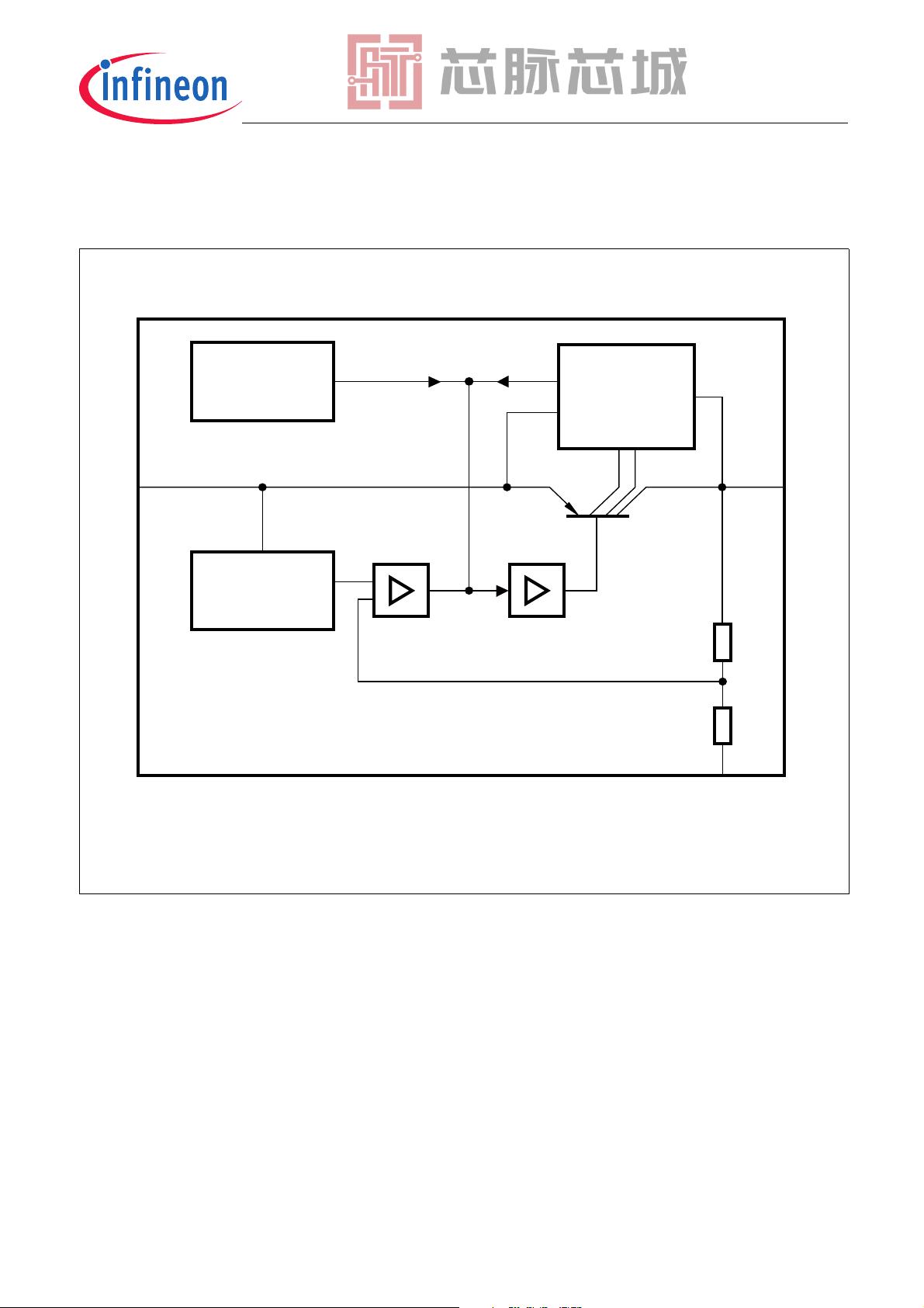
The TLE42744 is a monolithic integrated low dropout voltage regulator for load currents up to 400 mA. An input
voltage up to 40 V is regulated to
V
Q,nom
= 5 V / 3.3 V with a precision of ±2%. The device is designed for the harsh
environment of automotive applications. Therefore it is protected against overload, short circuit and
overtemperature conditions by the implemented output current limitation and the overtemperature shutdown
circuit. The TLE42744 can be also used in all other applications requiring a stabilized 5 V / 3.3 V voltage.
Due to its very low quiescent current the TLE42744 is dedicated for use in applications permanently connected to
V
BAT
.
TLE42744
Block Diagram
Data Sheet 3 Rev. 1.3, 2018-03-05
2 Block Diagram
Figure 1 Block Diagram
Ι
AEB01959
GND
Q
Bandgap
Reference
Control
Amplifier
Sensor
Temperature
Buffer
Saturation
Control and
Protection
Circuit
Data Sheet 4 Rev. 1.3, 2018-03-05
TLE42744
Pin Configuration
3 Pin Configuration
3.1 Pin Assignment PG-TO252-3, PG-TO263-3 and PG-SOT223-4
Figure 2 Pin Configuration (top view)
3.2 Pin Definitions and Functions PG-TO252-3, PG-TO263-3 and PG-SOT223-4
Pin No. Symbol Function
1IInput
block to ground directly at the IC with a ceramic capacitor
2GNDGround
internally connected to heat slug
3QOutput
block to ground with a capacitor close to the IC terminals, respecting the values given
for its capacitance and ESR in “Functional Range” on Page 6
4 / Heat Slug – Heat Slug
internally connected to GND;
connect to GND and heatsink area
AEP02561
13
Ι Q
GND
GND
Ι
Q
AEP02281
PinConfig_PG-SOT223-
4.vsd
123
4
I
GND
GND
Q
剩余20页未读,继续阅读
资源评论
芯脉芯城
- 粉丝: 3
- 资源: 4031
上传资源 快速赚钱
- 我的内容管理 展开
- 我的资源 快来上传第一个资源
- 我的收益 登录查看自己的收益
- 我的积分 登录查看自己的积分
- 我的C币 登录后查看C币余额
- 我的收藏
- 我的下载
- 下载帮助
安全验证
文档复制为VIP权益,开通VIP直接复制
信息提交成功