© 2013 Synopsys, Inc.
Developed By: Vazgen Melikyan
IC Synthesis Based on ARM® CortexTM-M0 DesignStart™ Processor
Lab 6: Placement
Theoretical part
1.1. IC Compiler (ICC) reads the design in .v, .ddc, .db formats:
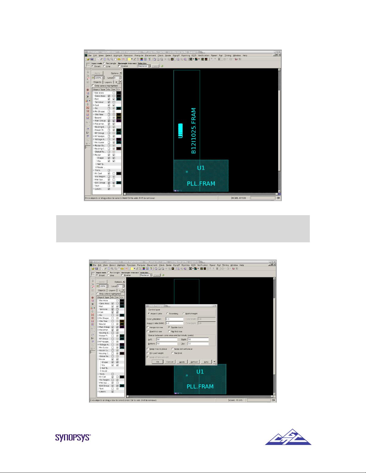
1.2. The core can be drawn with 4 parameters: aspect ratio, width and height, row number,
boundary.
�Aspect ratio is a ratio of height divided by width.
�Width & height are the exact width and height.
�Row number is the number of rows.
�Boundary is a fixed size according to the boundary defined in design planning.
Core utilization factor indicates the amount of core area used for cell placement. The number is
calculated as a ratio of the total cell area to the core area.
Aspect ratio (H/W): the aspect ratio must be entered for the core area.
Row/Core ratio: numbers from 0 to 1.0 indicate the amount of channel space provided
for routing between the cell rows. The smaller is the number, the more
space is left for routing.
Core width: the width of the core area must be entered in the user units.
Num rows: the number of cell rows must be specified.
Core height: the height of the core area in the user units must be specified.
1.3. After completing design planning and power planning placement and optimization are
performed. The place_opt command performs coarse placement, high-fanout net synthesis,
physical optimization and legalization.
1.4. After performing placement, the following can be analyzed:
� Placement congestion (report_congestion)
� Power (report_power)
� Timing (report_timing)
Practical part
2.1. Move to directory lab6/work.
2.2. Invoke ICC.
2.3. Setup logic libraries.
2.4. Set TLU+ files.
2.5. Create Milkyway library.
2.6. Read the design. Use File-Import Designs. The dialog box is shown in Fig. 1.
import_designs -format verilog "$verilog"
Fig. 1 Import design dialog box