


System Verilog Testbench Tutorial
Using Synopsys EDA Tools
Developed By
Abhishek Shetty
Guided By
Dr. Hamid Mahmoodi
Nano-Electronics & Computing Research Center
School of Engineering
San Francisco State University
San Francisco, CA
Fall 2011

2
Table of Contents
1. Introduction ........................................................................................................ 4
2. Building Blocks of Testbench ............................................................................. 5
2.1 Program Block ........................................................................... 7
2.2 The Interface ............................................................................ 8
2.3 Clocking Blocks ............................................................................ 10
2.4 Top Module ............................................................................. 13
2.5 Intermediate Blocks ............................................................................. 14
2.6 Working with Threads...Concept of Fork and Join ............................. 15
2.7 Randomization: What to randomize ..................................................... 15
2.8 Events, Semaphores .............................................................................. 16
2.9 Tasks and Functions ............................................................................. 18
3. System Verilog Assertions .................................................................................. 20
3.1 Types of Assertions ............................................................................ 21
3.1.1 Immediate Assertion ................................................................. 21
3.1.2 Concurrent Assertion ..................................................... 22
3.2 Implication Operator ........................................................................... 23
3.3 Types of Implication .......................................................................... 24
3.3.1 Overlapped Implication .................................................... 24
3.3.2 Non-overlapped Implication .................................................... 24
3.4 Mailboxes ........................................................................................ 25
3.5 Guide to write a System Verilog Verification Testbench ................ 26
3.6 Step-by-Step Layered Approach for System Verilog Testbench ......... 28
3.7 FIFO Example ............................................................................ 30
3.8 Advanced Topics with Router Example ........................................ 41
4. References & Books ........................................................................................ 42

3
Tables and Figures:
Fig 1: Building blocks of System Verilog
Fig 2: Program Block
Fig 3: Interface Demo
Fig 4: Clocking block Example
Fig 5: Signal Direction using Modport
Fig 6:Complete Interface Example
Fig 7: Fork and Join
Fig 8: Assertions Block Diagram
Fig 9: Immediate Assertions Example
Fig 10: Concurrent Assertions Example
Fig 11 - 18: Approach to develop FIFO Example
Fig 19: Makefile
Fig 20 - 23: Simulation Outputs

4
1. Introduction
The Verification Process
The process of verification parallels the design creation process. A designer reads the hardware
specification for a block, interprets the human language description, and creates the corresponding logic in
a machine-readable form, usually RTL code written using Verilog or VHDL language. To do this, the user
needs to understand the input format, the transformation function, and the format of the output. There is
always ambiguity in this interpretation, perhaps because of ambiguities in the original document, missing
details or conflicting descriptions. The SystemVerilog language provides three important benefits over
Verilog.
1. Explicit design intent – SystemVerilog introduces several constructs that allow you to explicitly state
what type of logic should be generated.
2. Conciseness of expressions – SystemVerilog includes commands that allow you to specify design
behavior more concisely than previously possible.
3. A high level of abstraction for design – The SystemVerilog interface construct facilitates inter module
communication.
These benefits of SystemVerilog enable you to rapidly develop your RTL code, easily maintain your code,
and minimize the occurrence of situations where the RTL code simulates differently than the synthesized
netlist. SystemVerilog allows you to design at a high level of abstraction. This results in improved code
readability and portability. Advanced features such as interfaces, concise port naming, explicit hardware
constructs, and special data types ease verification challenges.
Basic Testbench Functionality
The purpose of a Testbench is to determine the correctness of the design under test (DUT). The following
steps accomplish this.
• Generate stimulus
• Apply stimulus to the DUT
• Capture the response
• Check for correctness
• Measure progress against the overall verification goals
5
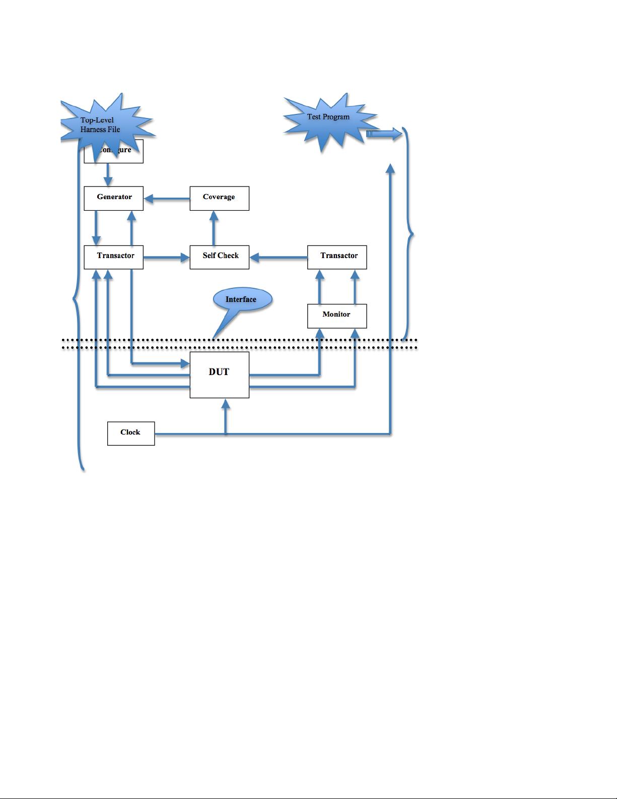
2. Building Blocks of Testbench
Fig 1
System Verilog Verification Features
These features assist in the creation of extensible, flexible test benches.
New Data Types:
int da[]; // dynamic array
int da[string]; // Associative array, indexed by string
int da[$]; // Queue
initial begin
da = new[16]; // Create 16 elements
end
The string data type represents a variable-length text string, which is a unique feature of System Verilog.
System Verilog offers dynamic arrays, associative arrays and queues. The array can be resized if needed.


