


Nonlinear F-16 Model
Description
L. Sonneveldt
Control & Simulation Divis ion
Faculty of Aerospace Engineering
Delft University of Technology
The Netherlands
Version 1.0, March 2010
Copyright
c
Control & Simulation Division, Delft University of Technology
All rights reserved L. Sonneveldt
1

Nomenclature
State variables:
V
T
= total velocity, m/s
α, = angle of attack, rad
β = angle of sideslip, rad
φ, θ, ψ = Euler angles, rad
q
0
, q
1
, q
2
, q
3
= quaternion components
p, q, r = body-axis roll, pitch and yaw rates, rad/s
x
E
, y
E
, z
E
= aircraft position w.r.t. reference point, m
pow = power setting, %
Control variables:
δ
th
= throttle setting, 0 − 1
δ
e
= elevator deflection, rad
δ
a
= aileron deflection, rad
δ
r
= rudder deflection, rad
δ
LEF
= leading edge flap defle ction, rad
Additional parameters
b = reference wing span, m
¯c = mean aerodynamic chord, m
C
∗
= Aerodynamic coefficient of *
F
T
= thrust force, N
g
1
, g
2
, g
3
= gravity components, m/s
2
H
eng
= engine angular momentum, kg.m
2
/s
I
x
, I
y
, I
z
= moments of inertia kg.m
2
I
xz
= product moment of inertia kg.m
2
¯
L,
¯
M,
¯
N = rolling, pitching and yawing moments, Nm
m = mass, kg
M = Mach number
p
s
= static pressure , P a
¯q = dynamic pre ssure, P a
S = reference wing surface area, m
2
T = Temperature, K
T
s/b
= Rotation matrix body-fixe d to stability-axes re ference frame
T
w/b
= Rotation matrix body-fixe d to wind-axes reference fra me
u, v, w = body-axis velocity components, m/s
¯
X,
¯
Y ,
¯
Z = axial, lateral and normal force components, N
x
cg
= center of gravity location, m
x
cg
r
= reference center of gravity location, m
γ = flight path angle, rad
ρ = air density, kg/m
3
2
1 Aircraft Dynamics
In this section the equations of motion for the F-16 model a re derived, this
derivation is based o n [1, 2, 3]. A very thorough discussion on flight dynamics
can be found in the course notes [4].
1.1 Reference Frames
The reference frames used in this thesis are the earth-fixed reference frame F
E
,
used as the inertial fra me and the vehicle carried local earth reference frame F
O
with its origin fixed in the center of gravity of the aircr aft which is assumed to
have the s ame orientation as F
E
; the wind-axes reference frame F
W
, obtained
from F
O
by three successive rotations of χ, γ and µ; the stability-axes reference
frame F
S
, obtained from F
W
by a rotation of −β; and finally the body-fixed
reference frame F
B
, obtained fr om F
S
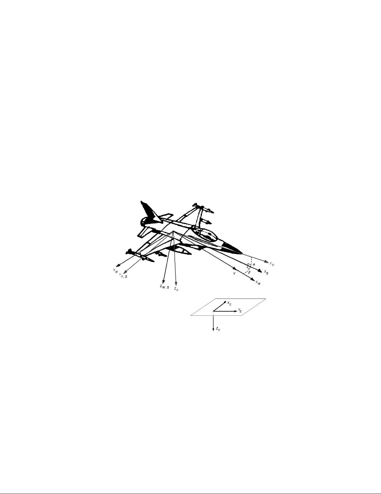
by a rotation of α as is also indicated in
Figure 1. The body-fixed reference frame F
B
can also be obtained directly from
Figure 1: Airc raft reference frames: earth-fixed reference frame F
E
, body-fixed
reference frame F
B
, sta bility-axes reference frame F
S
and wind-axes reference
frame F
W
F
O
by three suc cessive rotations o f yaw angle ψ, pitch angle θ and roll ang le
φ. All reference frames are right-handed and orthogonal. In the ear th- fixed
reference frame the z
E
-axis po ints to the center of the earth, the x
E
-axis po ints
in some arbitrary direction, e .g. the north, a nd the y
E
-axis is perpendicular to
the x
E
-axis.
3

The transformation ma trices from F
B
to F
S
and from F
B
to F
W
are defined as
T
s/b
=
cos α 0 sin α
0 1 0
− sin α 0 cos α
, T
w/b
=
cos α cos β sin β sin α cos β
− cos α sin β cos β − sin α sin β
− sin α 0 cos α
.
1.2 Aircraft Variables
A number of assumptions has to be made, before proceeding with the derivation
of the equations of motion:
1. The aircraft is a rigid-body, which means that any two points on o r within
the airframe remain fix ed with resp e ct to each other. This assumption is
quite valid for a small fighter aircraft.
2. The earth is flat and non-rotating and regarded as an inertial reference.
This assumption is valid when dealing with control design of aircraft, but
not when analyzing ine rtial g uidance systems.
3. The mass is constant during the time interval over which the motion is
considered, the fuel consumption is neglected during this time-interval.
This assumption is necessary to apply Newton’s motion laws.
4. The mass distribution of the aircraft is symmetric relative to the X
B
OZ
B
-
plane, this implies that the products of inertia I
yz
and I
xy
are equal to
zero. This assumption is valid for most aircraft.
Under the above assumptions the motion of the aircraft has six degrees o f free-
dom (rotation and translation in three dimensions). The aircraft dynamics can
be described by its position, orientation, velocity and angular velocity over time.
p
E
= (x
E
, y
E
, z
E
)
T
is the position vector expressed in an earth-fixed coordinate
system. V is the velocity vector given by V = (u, v, w)
T
, where u is the longitu-
dinal velocity, v the lateral velocity and w the normal velocity. The orientation
vector is given by Φ = (φ, θ, ψ)
T
, where φ is the roll angle, θ the pitch angle
and ψ the yaw angle , and the angula r velocity vector is given by ω = (p, q, r)
T
,
where p,q and r are the roll, pitch and yaw angular velocities, respectively. Va r-
ious components of the aircraft motions are illustrated in Figure 2.
The relation betwe en the attitude vector Φ and the angular velocity vec tor ω
is g iven as
˙
Φ =
1 sin φ tan θ cos φ tan θ
0 cos φ − sin φ
0
sin φ
cos θ
cos φ
cos θ
ω (1)
Defining V
T
as the total velocity and using Figure 2, the following relations can
be derived:
V
T
=
p
u
2
+ v
2
+ w
2
α = arcta n
w
u
(2)
β = arcsin
v
V
T
4

Figure 2: Aircraft orientation angles φ, θ and ψ, aerodynamic angles α and β,
and the angular rates p, q and r. All angles and rates are defined positive in the
figure.
Furthermore, when β = φ = 0, the flight path angle γ can be defined as
γ = θ − α (3)
1.3 Equations of Motion for a Rigid Body Air craft
The equations of motion for the a ircraft can be derived from Newton’s Sec ond
Law of motion, which s tates that the summation of all external force s acting
on a body must be equal to the time rate of change of its momentum, and the
summation of the external moments acting on a body must be equal to the time
rate of change of its angular momentum. In the inertial, Earth-fixed reference
frame F
E
, Newton’s Second Law can be expressed by two vector equations [4]
F =
d
dt
(mV)
i
E
(4)
M =
dH
dt
i
E
(5)
where F represents the sum of all externally applied for ces, m is the ma ss o f
the aircraft, M represents the sum of all applied torques and H is the angular
momentum.
1.3.1 Force Equation
First, to further evaluate the force equation (4) it is necessary to obtain an
expression for the time rate of change of the velocity vector with respect to
earth. This process is complicated by the fact that the velocity vector may be
rotating while it is changing in magnitude. Using the equation of C oriolis in
appendix A of [1] results in
F =
d
dt
(mV)
i
B
+ ω × mV, (6)
whereω is the total angular velocity of the aircraft with respect to the earth
(inertial reference frame). E xpressing the vectors as the sum of their components
5


评论2