
1
Educational Five-Bar Parallel Robot
Xavier Cano-Ferrer
Abstract
The present paper describes the design
of an educational five-bar parallel robot based
on the Teensy microcontroller. The small size of
the robot and the simplicity of its components
makes it suitable for its easy reproduction and
programming.
I. INTRODUCTION
Fiver-bar parallel robots have been studied in
academia for years. Some of their most common
applications are: drawing [1] [2] or engraving and
manipulation [3] [4]. The presented desktop sized
five-bar parallel robot (Figure 1) can be fully
laser cut, manufactured in one day and
programmed using the Arduino IDE and
Teensyduino. For these reasons, it can be a good
model to learn robotics concepts. The Robot
actuators are two stepper motors Nema 17. The
motors are driven by two A4988 Stepper Motor
Driver Carrier, Black Edition [5]. A Teensy 3.2
microcontroller [6] is the programmable “brain”
of the robot. Two limit switches [7] are located
on the limits of the workspace of the robot and are
used to perform the homing sequence of the
robot. A PCB has been designed to operate the
robot. All the dxf., step., stl. and Gerber files can
be download from the Hackaday project’s page.
The project started with a preliminary design
based on two Pololu 37D 50:1 geared brushed DC
motors sharing their shafts with two rotary
incremental encoders. In this first design, the
encoders were used to implement a PID position
controller for each actuated joint. The control
algorithm was programmed on an Arduino Mega
2650 and the motors were driven by the Pololu
Dual MC33926 Motor Driver Arduino Shield. On
the second design, the brushed DC motors were
replaced by stepper motors and the third design is
a hybrid of both. The robot is still designed to be
operated with the teensyStep library but it has the
incremental encoders coupled with the motor
shafts to be able to record desired trajectories. All
the information of the three designs can be found
on the Hackaday project page [8]. In this article
the third design will be treated.
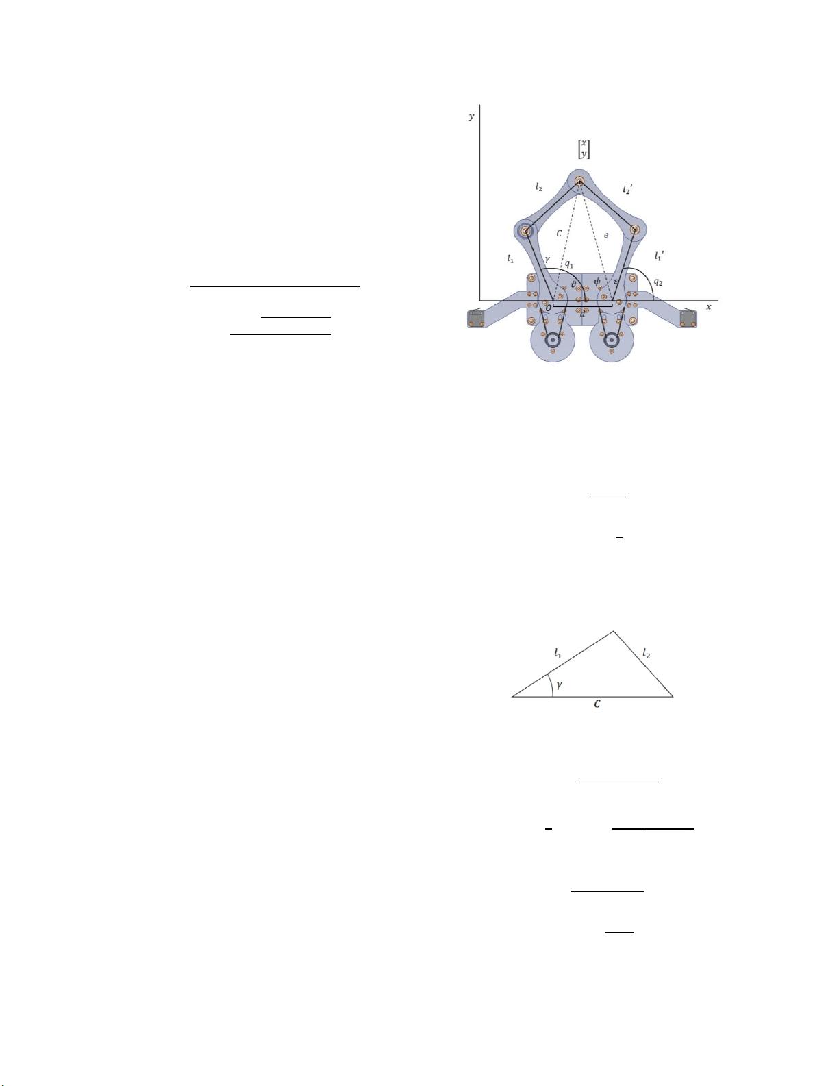
II. FORWARD KINEMATICS
The forward kinematic equations have been
adapted from Vathan et al. [9]. The equations can
be used on the program of the robot to evaluate
the position of the end effector of the robot for the
given angles
and
(Figure 2).
Figure 2: Forward kinematics diagram of the robot.
Figure 1: Five-bar parallel desktop robot manufactured
and asembled.