
Table of Contents
1 Features............................................................................1
2 Applications..................................................................... 2
3 Description.......................................................................3
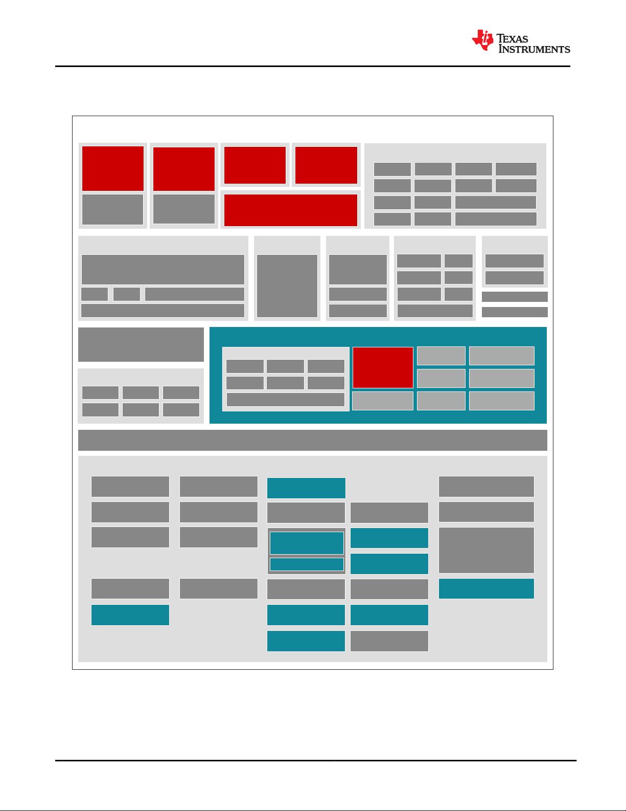
3.1 Functional Block Diagram........................................... 4
4 Revision History.............................................................. 5
5 Device Comparison......................................................... 8
5.1 Related Products.......................................................11
6 Terminal Configuration and Functions........................12
6.1 Pin Diagram.............................................................. 12
6.2 Pin Attributes.............................................................13
6.3 Signal Descriptions................................................... 81
6.4 Pin Multiplexing.......................................................137
6.5 Connections for Unused Pins................................. 152
7 Specifications.............................................................. 155
7.1 Absolute Maximum Ratings.................................... 155
7.2 ESD Ratings........................................................... 159
7.3 Power-On-Hour (POH) Limits................................. 159
7.4 Recommended Operating Conditions.....................159
7.5 Operating Performance Points................................162
7.6 Power Consumption Summary............................... 162
7.7 Electrical Characteristics.........................................163
7.8 VPP Specifications for One-Time Programmable
(OTP) eFuses............................................................170
7.9 Thermal Resistance Characteristics....................... 172
7.10 Timing and Switching Characteristics................... 173
8 Detailed Description....................................................290
8.1 Overview................................................................. 290
8.2 Processor Subsystems........................................... 291
8.3 Accelerators and Coprocessors..............................292
8.4 Other Subsystems.................................................. 294
9 Applications and Implementation.............................. 303
9.1 Power Supply Mapping........................................... 303
9.2 Device Connection and Layout Fundamentals....... 306
9.3 Peripheral- and Interface-Specific Design
Information................................................................ 308
10 Device and Documentation Support........................313
10.1 Device Nomenclature............................................313
10.2 Tools and Software............................................... 315
10.3 Documentation Support........................................ 316
10.4 Support Resources............................................... 316
10.5 Trademarks...........................................................316
10.6 Electrostatic Discharge Caution............................316
10.7 Glossary................................................................316
11 Mechanical, Packaging, and Orderable
Information.................................................................. 317
11.1 Packaging Information.......................................... 317
4 Revision History
Changes from July 22, 2021 to August 27, 2021 (from Revision I (July 2021) to Revision J
(August 2021)) Page
• Global:: Deleted "DMIPS" references................................................................................................................ 1
• (Device Comparison): Deleted "MCU Island with Lockstep Arm Cortex-R5Fs" row, as info in Lockstep and
Safety Targeted rows. ........................................................................................................................................ 8
• (Pin Attributes): Updated Buffer Types for MCU_PORz and PORz to FS Reset..............................................13
• Updated USB0/1_RCALIB note to indicate the pin must be connected with an external resistor to VSS even
when unused.................................................................................................................................................. 105
• Updated REXT pin note to show it should always be connected through an external resistor to VSS, even
when unused.................................................................................................................................................. 105
• Added clarification notes to MMC1_SDCD and MMC2_SDCD signals about pulled down requirement........ 111
• Updated CSI0 Signal Descriptions and CSI1 Signal Descriptions to show the RCALIB pins must be
connected to VSS through the external resistor even when unused.............................................................. 127
• (DSI_TX0 Signal Descriptions): Updated RCALIB pin description to show the pin must be connected to VSS
through an external resistor even when unused.............................................................................................127
• Added note indicting power balls should be connected to voltage specified in Recommended Operating
Conditions when unused................................................................................................................................ 133
• Added SERDES[0:4]_REXT rows in Connections for Unused Pins, these pins need to be connected to VSS
when unused.................................................................................................................................................. 152
• Showed VMON balls should be connected to PWR if unused in Connections for Unused Pins. Also added
note specifying MMC1_SDCD and MMC2_SDCD should be pulled down to function properly ....................152
• Showed CSI[1:0]_RXRCALIB, DSI_TXRCALIB, USB[1:0]_RCALIB pins should be connected to VSS is
unused in Connections for Unused Pins ........................................................................................................152
• Updated Specifications and removed note saying specifications are preliminary.......................................... 155
• (Speed Grade Maximum Frequency): Updated/Changed LPDDR4 frequency for L and E speed grades from
"4266" and "3733" MT/s to "3733" and "3200" MT/s, respectively................................................................. 162
• (Electrical Characteristics tables): Added FS Reset Electrical Characteristics Table..................................... 163
www.ti.com
TDA4VM-Q1, TDA4VM
SPRSP36J – FEBRUARY 2019 – REVISED AUGUST 2021
Copyright © 2021 Texas Instruments Incorporated
Submit Document Feedback
5
Product Folder Links: TDA4VM-Q1 TDA4VM


评论5