CAN introduction

Page 1
Introduction
CAN was developed for the automotive market to reduce the
weight and cost of wiring harnesses and add additional capabili-
ties. It is also used in factory automation, medical, marine,
military and anywhere a simple yet robust network is needed.
What Exactly is CAN ?
CAN, by itself, is not necessarily a complete network system. It
consists of only the physical layer (the two wires), the priority
scheme (highest priority message always gets through first) and
some error detection and handling circuitry. This allows simple
messages of from zero to eight bytes to be passed on the system.
CAN, like most modern networks, is serial based. This means
that the information travels along the network one bit at a time.
A CAN network needs from one to two lines depending on the
design. Parallel networks usually require more than 8 wires plus
several handshaking lines to facilitate the data transfer.
Most network systems using CAN will employ a higher level
protocol such J1939, CANopen or a proprietary scheme to create
and process messages over the basic CAN network.
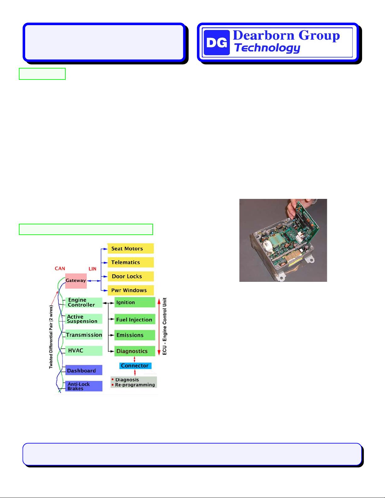
A Vehicle Network and its Components
Figure 1: CAN & LIN Automotive Network
Figure 1 has two buses connected together (CAN and LIN) by a
gateway that will be in one of the ECMs (Electronic Control
Module), depending on the design. Often the gateway is in the
ECU (Engine Control Unit). The ECU contains vital engine
CAN: Controller Area Network
Introduction and Primer
control functions and is often the clearinghouse for vehicle
diagnostics such as OBDII and/or a proprietary system. This is
a representative system and there are many other variations.
Engine Control Unit (ECU)
The Engine Control Unit is usually the most important module
in a vehicle and is central to the entire system. The ECU is also
another ECM. An ECU’s possible components are shown in the
four boxes on the right side of Figure 1.
The general term for vehicle modules in this article is ECM
(Electronic Control Module). Each ECM can exchange infor-
mation with other modules to accomplish certain tasks. For
instance, the transmission module will supply the speedometer
with the current speed as well as optionally to the radio to
modify the volume: this is transmitted over the CAN bus as
general network traffic. Figure 2 is an example of an ECM.
Figure 2: Toyota Airbag ECM
Communication Paths
CAN messages are broadcasted to all ECMs. There is generally
no way of knowing where a particular message came from or
where its intended destination ECM is.
This makes it easy to add another or different ECM to modify
vehicle features. The new ECM is simply plugged into the two
wire CAN bus and all other modules will see its messages.
Electronic Control Module Modes
A module can be in two general modes:
1) Standard: The modules and vehicle operate normally and
network traffic consists of ordinary data needed for the
operation of the vehicle. The translation of this data is
usually, but not always, proprietary to the manufacturer.
2) Diagnostic: The module is put into the diagnostic mode by a
scan tool that will make queries of the ECM. The ECM will
return information to the scan tool concerning problems with
the vehicle along with other data deemed important.
Copyright © 2004 Dearborn Group, Inc., September, 2004 Version 3.1
by Robert Boys rboys@dgtech.com
Phone (248) 488-2080 Fax (248) 488-2082
www.dgtech.com
Dearborn Group, Inc.
27007 Hills Tech Court, Farmington Hills, MI 48331
资源评论

 thanmail2012-02-28有点介绍的太浅显了,用处不大。


