没有合适的资源?快使用搜索试试~ 我知道了~
安捷伦公司官方的天线测试系统搭建方式,内容很好,对天线测试系统的搭建具有很好的指导意义
资源推荐
资源详情
资源评论
Agilent
Antenna Test
Selection Guide
2
1. Introduction ..........................................................................................................3
Use this guide to: ......................................................................................................................3
Main parts of an antenna range ............................................................................................ 4
Channel Partners .......................................................................................................................4
2.
Overview of antenna applications using Agilent PNA Series network analyzers
... 5
Near-field antenna measurements ........................................................................................ 6
Far-field antenna measurements ...........................................................................................7
Radar cross-section measurements ......................................................................................10
Banded millimeter-wave antenna configurations ...............................................................11
3. Antenna measurement design considerations ........................................................ 14
Transmit site configuration ..................................................................................................... 14
Receive site configuration with external mixing ................................................................. 19
Determining measurement speed .......................................................................................... 24
Optimizing speed and dynamic range ................................................................................... 25
PNA interface requirements ................................................................................................... 26
Functional test ...........................................................................................................................33
4. Migrating from 8510/8530 to PNA Series ................................................................. 34
Migration from 8510/8530 based antenna systems to PNA Series based systems. ..34
Engineering services provided for 8510/8530 migration to PNA Series
network analyzers . ................................................................................................................... 35
Migration examples . ................................................................................................................ 36
5. Antenna measurement components catalog ............................................................ 38
Microwave network analyzers ................................................................................................ 38
Sources .......................................................................................................................................42
Frequency converters ............................................................................................................... 44
Amplifiers ....................................................................................................................................57
Multiple-channel measurements ...........................................................................................59
Measurement automation ....................................................................................................... 63
Appendix 1: PNA
Series
security features ...................................................................... 64
Terms and definitions ...............................................................................................................64
PNA memory .............................................................................................................................. 65
Memory clearing, sanitization and/or removal procedures ..............................................65
User and remote interface security measures ....................................................................66
Procedure for declassifying a faulty instrument ................................................................. 67
Appendix 2: How to select PNA
Series
IF BW with performance
comparable to 8510 ................................................................................................................68
Appendix 3: How to configure an external source for use with a PNA
Series
..... 69
Table of Contents
3
Agilent Technologies provides many of the components you need to make accurate
antenna and radar cross-section (RCS) measurements. This Antenna Test Selection
Guide will help you select the hardware necessary to meet your antenna measurement
requirements. This note is primarily for customers who want to design, integrate, and
install their own antenna measurement system using Agilent antenna test equipment,
and for customers migrating to Agilent’s latest network analyzers. For the experienced
do-it-yourself customer, this selection guide will describe the input and output charac-
teristics of antenna measurement components available through Agilent. Your Agilent
Technologies sales engineer will be glad to assist you in procuring the instrumentation.
Agilent Technologies does not provide software or integration services for antenna
measurement systems. However, Agilent Productivity Services can provide these
services for a fee.
Some customers may prefer the design, integration, and installation of an antenna
system be performed for them by a solution supplier who has extensive antenna test
configuration experience. Agilent Technologies works with channel partners who can
provide this service. Our channel partners will work with you to understand your
measurement needs and design an antenna test system that meets those needs. They
will design the RF subsystem, the positioning subsystem, the measurement application
software, and provide system installation and training.
This selection guide is meant as an aid for those with extensive antenna test
experience. Refer to the Agilent website: www.agilent.com/find/antenna for access to
technical papers and current antenna test equipment information.
Use this guide to:
• Understand how Agilent instruments can be integrated into your configuration
• Learn about interface requirements between components
• Understand issues related to selecting the equipment required to make antenna
measurements
• Learn how to migrate from the 8510 to PNA network analyzer or 8530 to N5264A
PNA-X measurement receiver.
1. Introduction
Main parts of an antenna range
A typical antenna range measurement system can be divided into two separate parts:
the transmit site and the receive site (see Figure 1). The transmit site consists of the
microwave transmit source, amplifiers (optional), the transmit antenna, and the com-
munications link to the receive site. The receive site consists of the antenna under test
(AUT), a reference antenna, receiver, LO source, RF downconverter, positioner, system
software, and a computer.
Figure 1. Simplified far-field antenna range example with MXG Source and N5264A PNA-X
Measurement Receiver with LO source (Opt 108).
Channel Partners
Agilent works with channel partners who develop complete antenna test and antenna
range solutions. These partners build and install antenna measurement systems working
with Agilent engineers to solve customer problems. Agilent instruments such as
measurement receivers, network analyzers, sources and accessories, are sold either
directly to the end-user or through Agilent channel partners. Contact your Agilent sales
representative for a channel partner in your local area.
4
Transmit site
Receive site
5
The Agilent PNA-X measurement receiver and PNA/PNA-X series network analyzers
incorporate new technologies and features to provide better performance and capabili-
ties for antenna and radar cross-section (RCS) test applications.
High sensitivity
The Agilent PNA-X measurement receiver is a direct replacement for the previous 8530A
model with fast throughput and higher measurement sensitivity.
The PNA/PNA-X analyzer has a mixer-based architecture providing excellent sensitiv-
ity. With the PNA/PNA-X series, you have the ability to select from a minimum of 29
different IF bandwidths. This allows you to optimize the sensitivity versus measurement
speed tradeoff to fit particular measurement and application requirements.
With the PNA-X series analyzer, you can maximize sensitivity with remote mixing by
adding Option 020, IF Access. This option allows you to use an externally generated
7.606 MHz IF and bypass the PNA-X’s internal first down-converter. Front loops can
also improve sensitivity by about 15 dB by bypassing the coupler.
PNA series analyzers provide maximum sensitivity with remote mixing by adding Option
H11, IF Access. This option allows you to use an externally generated 8.33 MHz IF and
bypass the PNA’s internal first down-converter. Option 014 can also improve sensitivity
by about 15 dB by adding reference links that allow you to bypass the coupler.
Increased speed
Extremely fast data transfer rates with the network analyzers are accomplished using
the COM/DCOM features. LAN connectivity through a built-in 10/100 Mb/s LAN inter-
face enables the PC to be distanced from the test equipment. Together these features
provide remote testing and reduced test time.
Option 118 ads fast CW mode and provides a data acquisition speed of more than
400,000 points per second; with up to five measurement receivers simultaneously.
Flexibility and accuracy
Up to five simultaneously test receivers (A, B, C, D and R) are available in the PNA-X
measurement receiver, four receivers in PNA/PNA-X standard, and five receivers in
PNA-X option 020; with each receiver capable of measuring up to 400,000 points of data.
Option 080 enables the PNA/PNA-X series analyzers to set the source frequency
independently from where the receivers are tuned. The user may enter multiplier and
offset values to describe how the instrument’s receivers track the source frequency.
With Option 080, PNA reference receiver power levels can be below the phase lock
level since phase locking is performed separately. You can attain exceptionally accu-
rate antenna measurements by combining Option H11, IF access, with Option 080,
Frequency-offset capability and advanced triggering.
PNA-X measurement receivers and PNA/PNA-X analyzers support synchronization with
external signal generators which can further enhance performance and greatly improve
measurement accuracy.
Pulsed measurements
PNA-X Series Option 020 port-one internal modulator and 025 internal pulse generators
add pulsed-RF for pulsed antenna test applications. PNA Series Option H11 adds inter-
nal receiver gates for use in pulsed-RF and pulsed antenna test applications. Combined
with Option H08, these gates augment the PNA’s pulse measurement capability by
enabling point-in-pulse testing, with pulse widths smaller than 100 ns.
Security
For secure environments, the PNA family features a removable hard drive to completely
ensure the security of the data that is acquired by the PNA. Refer to “Appendix 1” on
page 64 for detailed information.
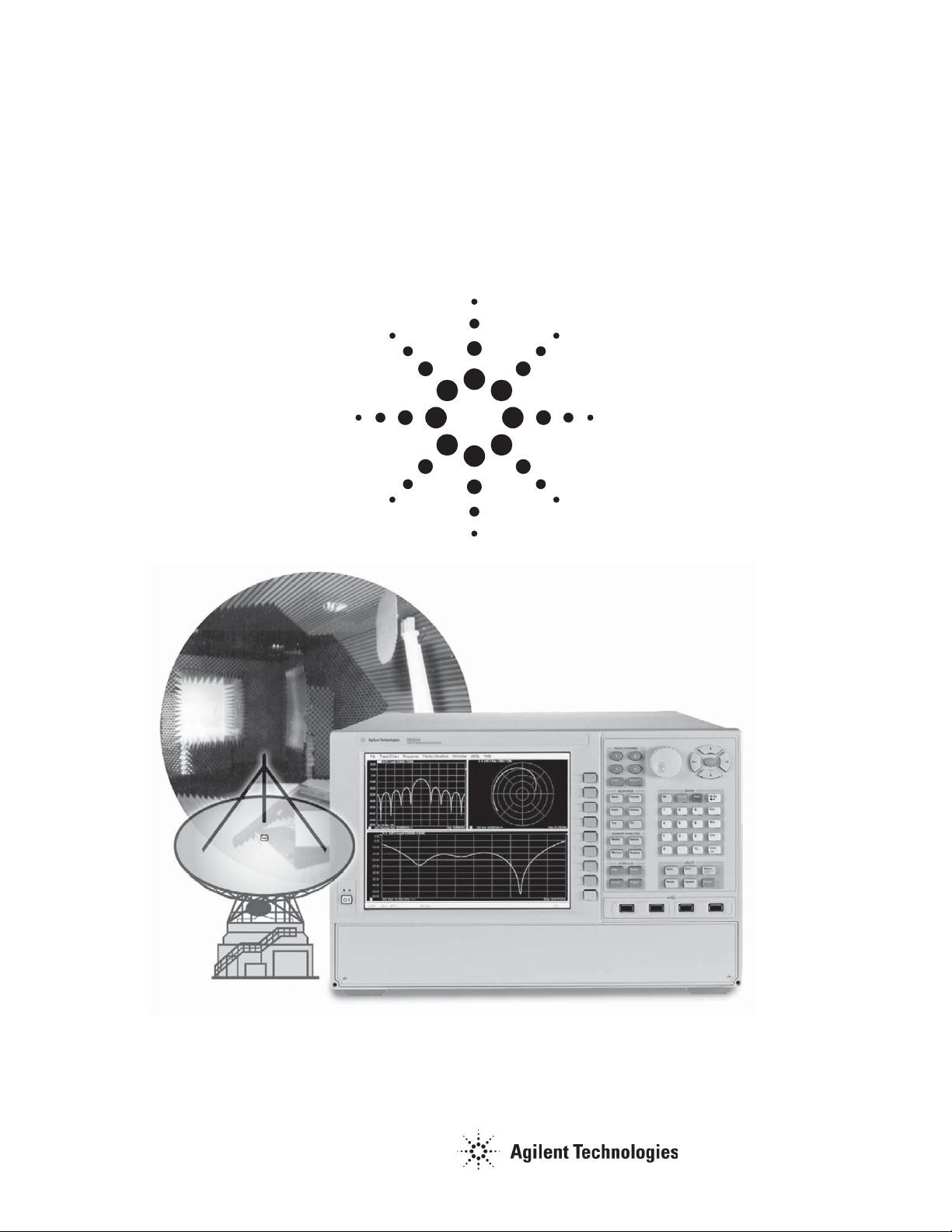
The following sections demonstrate how the PNA can be integrated into your near-field,
far-field, RCS, and millimeter-wave systems.
2. Overview of antenna
applications using
Agilent PNA Series
network analyzers
剩余73页未读,继续阅读
资源评论
nudtleox
- 粉丝: 0
- 资源: 5
上传资源 快速赚钱
- 我的内容管理 展开
- 我的资源 快来上传第一个资源
- 我的收益 登录查看自己的收益
- 我的积分 登录查看自己的积分
- 我的C币 登录后查看C币余额
- 我的收藏
- 我的下载
- 下载帮助
最新资源
- python代码案例详解-旅行商问题的多种求解算法.zip
- springcloud.rar
- 一键清理maven项目依赖下载失败生成的.lastUpdated文件, 以及解决无法连接远程仓库导致本地依赖找不到的批处理脚本
- C#+WPF开发IOC框架实战架构师课程
- 《JAVA WEB项目开发案例精粹》中的代码案例源文件(超全).rar
- 背景music,用作业网轮地址
- comment_6e56cd5d6e140046ef1cd248910ea5ca.png
- 基于卷积神经网络的自动驾驶系统的设计与实现
- MySQL的执行原理-2.md
- 基于 FCN 网络对无人机俯拍下的生活场景语义分割(12类别)【包含数据集、完整代码、训练好的结果、权重文件等等】
资源上传下载、课程学习等过程中有任何疑问或建议,欢迎提出宝贵意见哦~我们会及时处理!
点击此处反馈
安全验证
文档复制为VIP权益,开通VIP直接复制
信息提交成功