没有合适的资源?快使用搜索试试~ 我知道了~
资源推荐
资源详情
资源评论
Altera Corporation 1
AN-455-1.0 Preliminary
Application Note 455
Understanding CIC
Compensation Filters
Introduction
The cascaded integrator-comb (CIC) filter is a class of hardware-efficient
linear phase finite impulse response (FIR) digital filters. CIC filters
achieve sampling rate decrease (decimation) and sampling rate increase
(interpolation) without using multipliers. Altera’s CIC Compiler
MegaCore
®
function implements various CIC filters based on
Hogenauer’s method.
f CIC filters were first proposed by Eugene Hogenauer in 1981, For more
information about CIC filters, refer to Eugene B. Hogenauer, “An
economical class of digital filters for decimation and interpolation,” IEEE
Transactions on Acoustics, Speech and Signal Processing, pp. 155-162, April
1981.
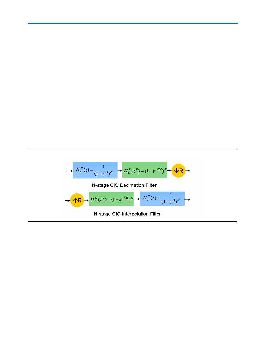
A CIC filter consists of an equal number of stages of ideal integrator filters
and comb filters. Its frequency response may be tuned by selecting the
appropriate number of cascaded integrator and comb filter pairs. The
highly symmetric structure of a CIC filter allows efficient implementation
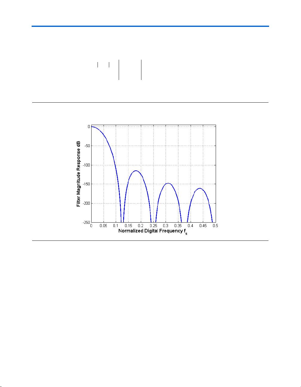
in hardware. However, the disadvantage of a CIC filter is that its pass
band is not flat, which is undesirable in many applications. Fortunately,
this problem can be alleviated by a compensation filter.
This application note presents theory and methods for designing CIC
compensating filters for sample rate conversion systems. The MATLAB
Signal Processing Toolbox is used to design the coefficients of the
compensating FIR filters. This application note also describes how to
choose parameters for designing a compensation filter and then
implements an example decimation system using the Altera
®
CIC
Compiler MegaCore function and the FIR Compiler MegaCore function.
The following topics are discussed in this document:
■ “Prerequisites” on page 2
■ “CIC Filter Structure” on page 2
■ “CIC Compensation Filter Design” on page 4
■ “Data Rate Down Conversion Example” on page 11
■ “Conclusion” on page 17
April 2007, ver. 1.0
2 Altera Corporation
Preliminary
Understanding CIC Compensation Filters
Prerequisites
This document targets digital signal processing (DSP) systems engineers
who must design CIC compensation filters for rate conversion systems.
A basic knowledge of DSP and digital filter design will help you
understand the trade-off between various CIC compensation filter design
methods.
In addition, to understand and duplicate the examples and figures used
in this application note, you should have the following:
■ Some experience with MATLAB and SIMULINK
■ Some knowledge of Altera DSP Solutions, including DSP Builder
1 The design example used in this application note can be
found at:
www.altera.com/support/examples/dsp-builder/
exm-digital-down-conv-cic-fir.html
CIC Filter
Structure
The basic elements of a CIC filter are integrator filters and comb filters, as
shown in Figure 1.
Figure 1. Block Diagram of Three-Stage CIC Decimation and Interpolation Filters
Altera Corporation 3
Preliminary
CIC Filter Structure
An integrator filter is a single pole accumulator with a transfer function
H
I
(z) (Equation 1):
(1)
A comb filter is a differentiator with a transfer function H
C
(z)
(Equation 2):
(2)
In this equation, M is the differential delay, and is usually limited to 1 or 2.
In a CIC filter, the integrators operate at high sampling frequency (f
S
), and
the comb filters operate at low frequency (f
S
/R). Using the Noble
identities, the equivalent frequency response of their cascade can be
calculated (Figure 2).
Figure 2. Block Diagram of the Equivalent Frequency Response of an N-Stage CIC Filter
Equation 3 shows the total response of a CIC filter at high frequency (f
S
):
(3)
In this equation, N is the number of integrator-comb filter pairs, and R is
the rate change factor. Equation 3 implies that the equivalent time domain
impulse response of a CIC filter can be viewed as a cascade of N
rectangular pulses. Each rectangular pulse has RM taps.
H
I
z()
1
1 z
1–
–
----------------
=
H
c
z() 1 z
M–
–=
Hz() H
I
N
z()H
c
N
z
R
() z
k–
k0=
RM 1–
∑
⎝⎠
⎜⎟
⎜⎟
⎛⎞
N
==
4 Altera Corporation
Preliminary
Understanding CIC Compensation Filters
Equation 4 shows the magnitude response of an N-stage CIC filter at high
frequency (f
S
):
(4)
Figure 3 shows an example of a CIC filter magnitude response:
Figure 3. Magnitude Response of a CIC Filter with N = 9, R = 8, and M = 1
f For more information about CIC filters, refer to Matthew Donadio,
Cascaded Integrator-Comb (CIC) Filter Introduction, available at
www.dspguru.com/info/tutor/cic.htm.
CIC
Compensation
Filter Design
Figure 3 shows that when the number of stages is large, the CIC filter
frequency response does not have a wide, flat pass band. To overcome the
magnitude droop, a FIR filter that has a magnitude response that is the
inverse of the CIC filter can be applied to achieve frequency response
correction. Such filters are called “compensation filters.”
For data rate down conversion, the compensation filter follows the CIC
filter. For up sampling systems, the compensation FIR filter
pre-conditions the data and is followed by a CIC filter. In other words, the
compensation filter always operates at the lower rate in a rate conversion
Hf()
π
Mf()sin
πf
R
---- -
⎝⎠
⎛⎞
sin
-----------------------
N
=
剩余16页未读,继续阅读
资源评论
meic266
- 粉丝: 0
- 资源: 19
上传资源 快速赚钱
- 我的内容管理 展开
- 我的资源 快来上传第一个资源
- 我的收益 登录查看自己的收益
- 我的积分 登录查看自己的积分
- 我的C币 登录后查看C币余额
- 我的收藏
- 我的下载
- 下载帮助
最新资源
- PHP端通过modbus协议跟第三方设备进行数据通信
- navicat安装包亲测可用
- 算法部署-使用OpenVINO部署MobileStyleGAN轻量化高保真图像合成算法-项目源码-优质项目实战.zip
- 基于java实现远程采集华为逆变器使用modbus tcp协议进行通讯的设备数据
- Unity画面共享Spout插件
- 基于C++用modbus实现的工业设备的数据采集程序,支持Tcp、串口
- 完结12章AI Agent智能应用从0到1定制开发
- 15白落梅:你是锦瑟我为流年:三毛的万水千山-3491776.mobi
- Federated Learning-Aided Prognostics in the Shipping 4.0: Princi
- OFDM 的鲁棒频率和定时同步文献部分阅读笔记
资源上传下载、课程学习等过程中有任何疑问或建议,欢迎提出宝贵意见哦~我们会及时处理!
点击此处反馈
安全验证
文档复制为VIP权益,开通VIP直接复制
信息提交成功