


UNIVERSITY OF TOULON
December 22, 2023
Modeling and Control of Underwater Vehicle: SPARUS
By:
Abubakar Aliyu BADAWI
N
o
´etudiant: 022303696

Contents
1 Introduction 1
1.1 Aim . . . . . . . . . . . . . . . . . . . . . . . . . . . . . . . . . . . . . . . . . . . . . . . 1
1.2 Objectives . . . . . . . . . . . . . . . . . . . . . . . . . . . . . . . . . . . . . . . . . . . . 1
2 Coordinate Frame Definition for the Sparus AUV 2
3 The Dimension of Different Bodies of the Sparus AUV 2
4 Analysis of Terms in the Global Real Mass Matrix for the Sparus AUV 4
4.1 Conclusion: . . . . . . . . . . . . . . . . . . . . . . . . . . . . . . . . . . . . . . . . . . . 6
5 Analyzing the Order of Magnitude of the Rigid Body Real Mass Matrix 7
6 Numerical Computation of Added Mass Matrices at the Buoyancy Center for
Sparus AUV 8
6.1 Conclusion: . . . . . . . . . . . . . . . . . . . . . . . . . . . . . . . . . . . . . . . . . . . 12
7 Comparing the added mass matrix at CG and CB 12
7.1 Conclusion: . . . . . . . . . . . . . . . . . . . . . . . . . . . . . . . . . . . . . . . . . . . 12
8 Comparing the Value of the Main Solid with Other Bodies 13
8.1 Conclusion: . . . . . . . . . . . . . . . . . . . . . . . . . . . . . . . . . . . . . . . . . . . 14
9 Comparing the Value of the Added Mass and Real Mass Matrices 14
9.1 Comparing the Mass (M11): . . . . . . . . . . . . . . . . . . . . . . . . . . . . . . . . . . 14
9.2 Conclusion: . . . . . . . . . . . . . . . . . . . . . . . . . . . . . . . . . . . . . . . . . . . 15
10 Computing the Drag Matrices 15
10.1 Conclusion: . . . . . . . . . . . . . . . . . . . . . . . . . . . . . . . . . . . . . . . . . . . 17
11 Validating the Simulator 17
11.1 Derive the dynamic equation parameters . . . . . . . . . . . . . . . . . . . . . . . . . . . 17
11.2 Validating the Model . . . . . . . . . . . . . . . . . . . . . . . . . . . . . . . . . . . . . . 19
11.3 Experiment 1: All Three Thrusters Off . . . . . . . . . . . . . . . . . . . . . . . . . . . . 20
11.4 Experiment 2: only vertical thruster ON . . . . . . . . . . . . . . . . . . . . . . . . . . . 20
11.5 Experiment 3: Left and Right thrusters ON . . . . . . . . . . . . . . . . . . . . . . . . . 20
11.6 Experiment 4: All thrusters powered . . . . . . . . . . . . . . . . . . . . . . . . . . . . . 21
12 Analyzing the Impact of Coefficients on Global Mass Matrix through Simulation
under Imposed Linear Acceleration. 22
12.1 Case 1: Motion along X-direction (Surge) . . . . . . . . . . . . . . . . . . . . . . . . . . 22
12.2 Case 2: Motion along Y-direction (Sway) . . . . . . . . . . . . . . . . . . . . . . . . . . 22
12.3 Case 3: Motion along Z-direction (Heave) . . . . . . . . . . . . . . . . . . . . . . . . . . 23
12.4 Conclusion . . . . . . . . . . . . . . . . . . . . . . . . . . . . . . . . . . . . . . . . . . . 23
13 Simulating the Influence of Drag Forces by Evaluating the Effects Under Constant
Linear Speed. 24
13.1 Conclusion . . . . . . . . . . . . . . . . . . . . . . . . . . . . . . . . . . . . . . . . . . . 25

14 CODE GUIDE 25
List of Figures
1 The Sparus AUV . . . . . . . . . . . . . . . . . . . . . . . . . . . . . . . . . . . . . . . . 1
2 The Sparus AUV frames . . . . . . . . . . . . . . . . . . . . . . . . . . . . . . . . . . . . 2
3 Top View Dimensions of the Sparus AUV . . . . . . . . . . . . . . . . . . . . . . . . . . 3
4 Side View Dimensions of the Sparus AUV . . . . . . . . . . . . . . . . . . . . . . . . . . 3
5 Exploded View Dimensions of the Sparus AUV . . . . . . . . . . . . . . . . . . . . . . . 9
6 Model Behaviour with all Thrusters OFF. . . . . . . . . . . . . . . . . . . . . . . . . . . 20
7 Model Behaviour with only vertical Thruster. . . . . . . . . . . . . . . . . . . . . . . . . 21
8 Model Behaviour with Left and Right Thrusters ON. . . . . . . . . . . . . . . . . . . . . 21
9 Model Behaviour with all Thursters ON . . . . . . . . . . . . . . . . . . . . . . . . . . . 22
10 Impact of the surge motion on different coefficients in the global mass matrix. . . . . . . 23
11 Impact of the sway motion on different coefficients in the global mass matrix. . . . . . . 23
12 Impact of the yaw motion on different coefficients in the global mass matrix. . . . . . . 24
13 Model Behaviour with Zero Drag Force. . . . . . . . . . . . . . . . . . . . . . . . . . . . 24
List of Tables
1 Saprus AUV Body Parts and their Dimensions . . . . . . . . . . . . . . . . . . . . . . . 4
1 Introduction
The Sparus AUV is a high-tech underwater vehicle with advanced features for exploring and researching
underwater areas. In this project, I’m closely studying how the Sparus AUV moves in the water,
focusing on figuring out things like its added mass and drag. By carefully creating models and using
simulations, I hope to understand better how the Sparus AUV behaves underwater and what it can
do.
Figure 1: The Sparus AUV
1.1 Aim
To gain in depth understanding of underwater robotics through the modeling and control of the Sparus
Autonomous Underwater Vehicle (AUV).
1.2 Objectives
This project aims to formulate the parameters essential for characterizing the dynamic equations of
the Sparus Autonomous Underwater Vehicle (AUV). Furthermore, I will validate these parameters
through simulations in MATLAB. This foundational exploration seeks to enhance my understanding
of the Sparus AUV’s dynamic behavior through the steps below:
1. Analyzing the magnitude and order of the global real mass matrix of the Sparus AUV
2. Computing the added mass matrix and the buoyancy center of the Sparus and comparing it to
that of the gravity center.
3. Comparing the added mass matrix of the main solid with other bodies and conclude.
4. Estimation of all drag matrices.
5. Complete and validate the simulator.
6. Investigating the impact of the different coefficients in the global mass matrix.
7. Investigating the impact of the drag forces of the different bodies
1
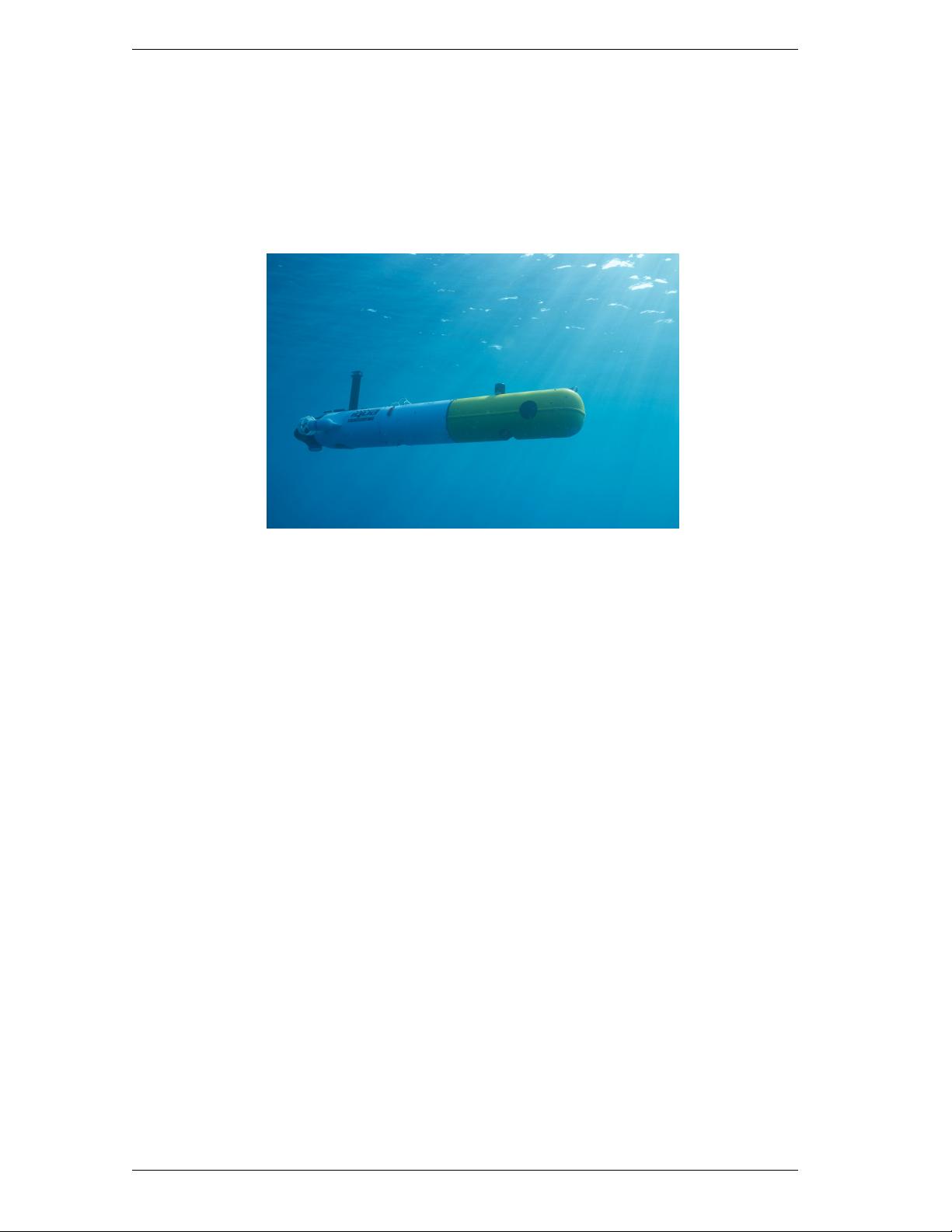
2 Coordinate Frame Definition for the Sparus AUV
The Sparus has its origin frame, denoted as (F
b
) established at the system’s midpoint. In this
frame, the x-axis of F
b
is positioned between the two thrusters, pointing towards the hemisphere
section of the Sparus, while the z-axis extends towards the opposite side of the antenna, as
illustrated in Figure below.
Figure 2: The Sparus AUV frames
In this experiment, I establish the origin of the Sparus body to coincide with the model’s center
of gravity. The distance from the origin of F
b
to the center of buoyancy is provided below.
r
b
cg
=
0
0
0
m
r
b
bu
=
0
0
−0.02
m
3 The Dimension of Different Bodies of the Sparus AUV
To compute the dimensions of the different bodies, I followed the following steps:
• Split the Sparus prototype into 7 parts as shown in Table 1 and Figure 4 below.
• Measure the dimension of each part on the given figure using the AutoCAD software.
• Multiply the measurements taken by the ruler by the following scale factors to get the
actual measurements:
The scale factor for the X-axis is given by:
X axis =
1600 mm
1703, 93 mm
= 0.9390
2


