没有合适的资源?快使用搜索试试~ 我知道了~
资源推荐
资源详情
资源评论
Template For ENG STDS
WORLDWIDE
ENGINEERING
STANDARDS
General Specification GMW17753
GM Extension to SAE J2534 Standard to Support CAN FD
© Copyright 2017 General Motors Company All Rights Reserved
January 2017
Page 1 of 16
1 Introduction
Note: Nothing in this standard supercedes applicable laws and regulations.
Note: In the event of conflict between the English and domestic language, the English language shall take
precedence.
1.1 Purpose. This purpose of this standard is to define an implementation of the Controller Area Network with
Flexible Data (CAN FD) protocol within the framework of SAE J2534-2, V04.04. This implementation utilizes the
manufacture discretionary features defined in the SAE J2534 standard. The intent is to add support of the
CAN FD protocol with minimal changes to existing applications and interfaces. The CAN FD protocol
implemented two (2) strategies to increase data throughput of a Controller Area Network (CAN) 2.0 network:
• Increased frame payload size to 64 Bytes.
• Higher Baudrates (5 Mpbs).
Also included in this standard are enhancements to the ISO 15765-2 protocol that were necessary to support
CAN FD:
• Configurable Frame Size.
• Increased Message Size.
1.2 Applicability. This document describes hardware and software changes required to add CAN FD to an
SAE J2534-1/SAE J2534-2 interface. It also serves a reference guide for application developers that wish to add
CAN FD support while staying within the framework of J2534, V04.04.
1.3 Remarks.
• References to “J1962” throughout the document relate to the SAE J1962 Diagnostic Connecter for On-Board
Diagnostic purposes.
• References to “J2284” throughout the document relate to SAE J2284 and are use-case specific. Care should
be exercised to apply the proper specification (see 2.1) for each application.
• References to “J2534” throughout the document relate to SAE J2534 and are use-case specific. Care should
be exercised to apply the proper specification (see 2.1) for each application.
2 References
Note: Only the latest approved standards are applicable unless otherwise specified.
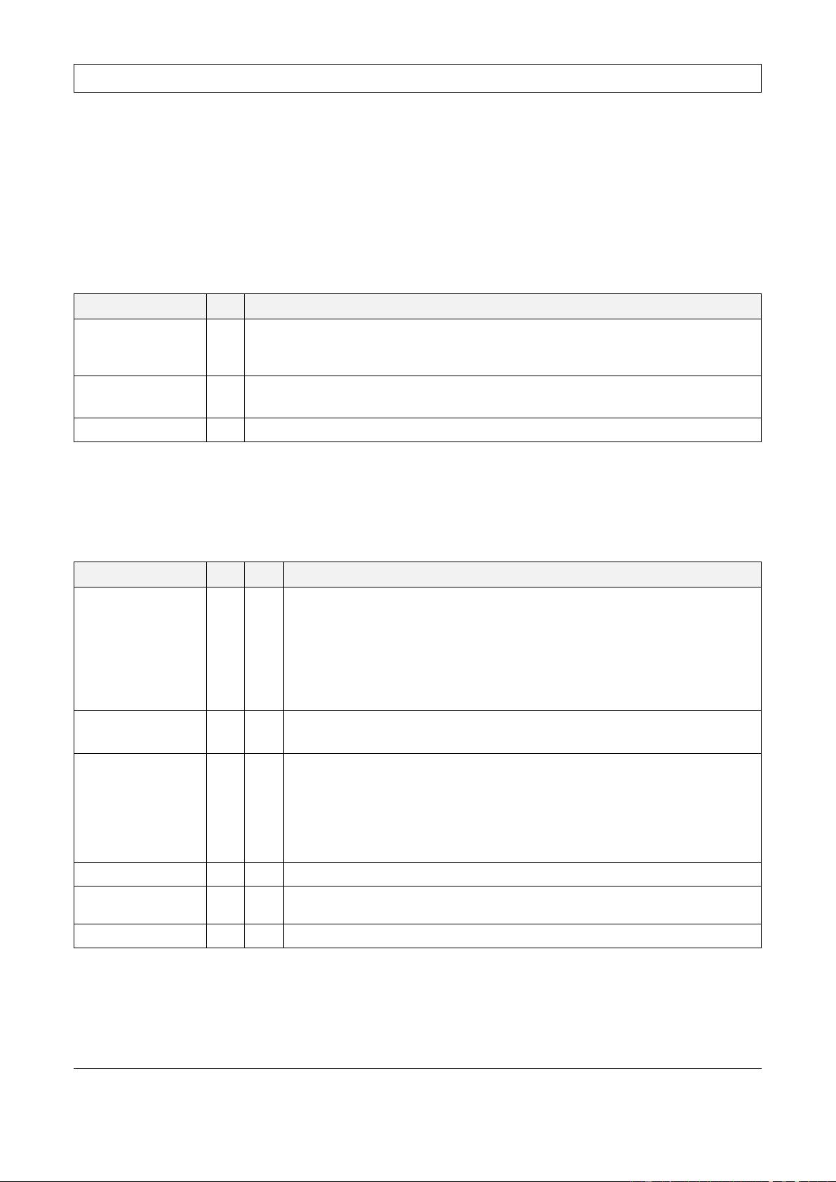
2.1 External Standards/Specifications.
ISO 11898-1
SAE J1962
SAE J2284-1
SAE J2284-4
ISO 11898-2
SAE J2534-1
SAE J2284-2
SAE J2284-5
ISO 15765-2
SAE J2534-2
SAE J2284-3
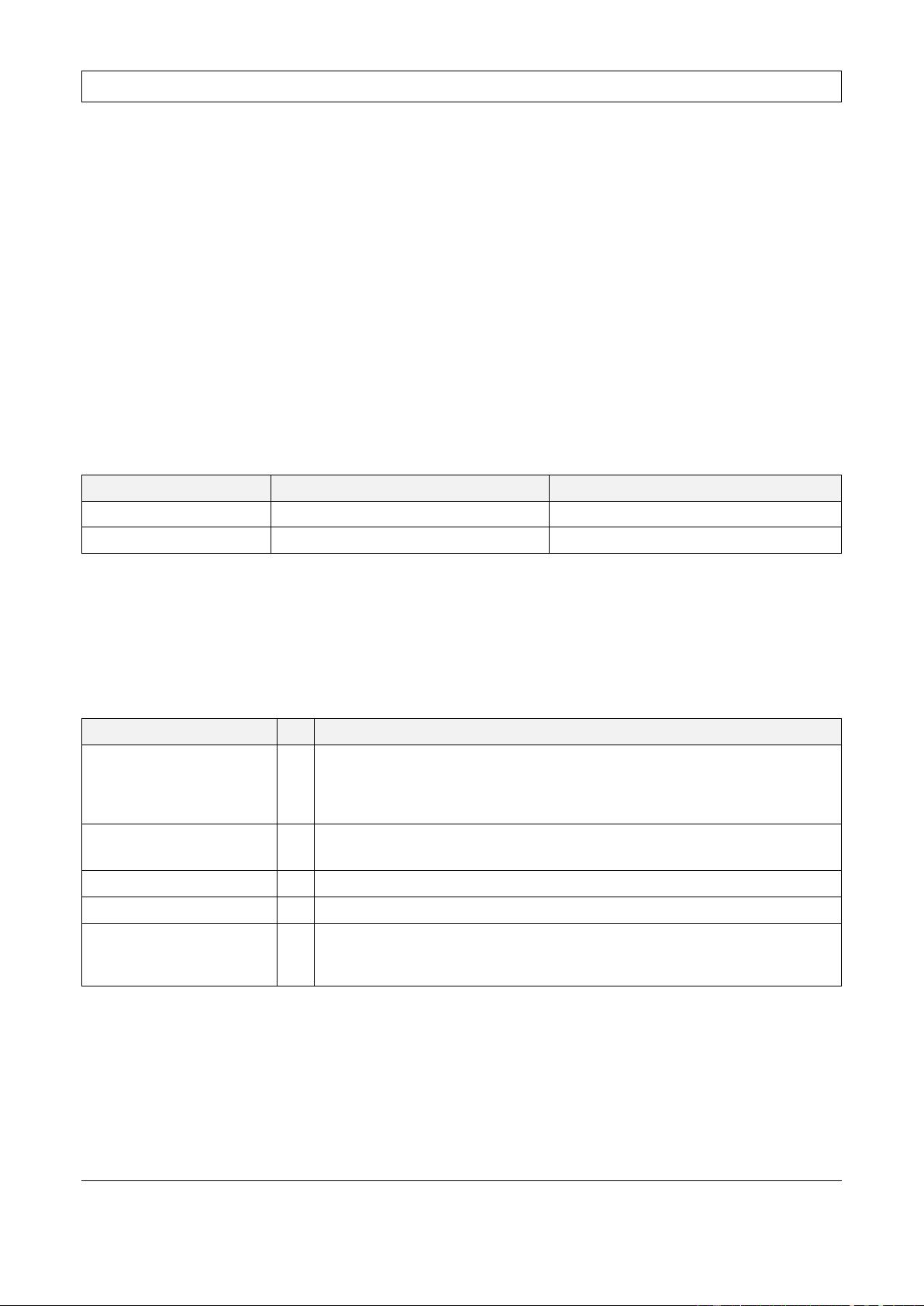
2.2 GM Standards/Specifications.
GMW3059
2.3 Additional References.
Bosch CAN FD specification: CAN with Flexible Data-Rate, Specification Version 1.0 (released April 17, 2012)
Copyright General Motors Company
Provided by IHS Markit under license with General Motors Company
Order Number: W2064747
Sold to:SHANGHAI DING AUTOMATION LLC. [213189100001] - CHANGMAO.WU@DING-AUTO.COM
Not for Resale,2018-02-13 01:36:59 UTC
Reproduction, distribution or publication of these standards is expressly prohib
--``````,,,,,,`,``,`,``-`-``,```,,,`---
GM WORLDWIDE ENGINEERING STANDARDS
Template For ENG STDS
GMW17753
© Copyright 2017 General Motors Company All Rights Reserved
January 2017
Page 2 of 16
3 Requirements
Unless indicated otherwise, the SAE J2534, V04.04 definitions of requirements, restrictions and error conditions
for Controller Area Network Pin Select (CAN_PS) and ISO15765_PS protocols will apply to CAN_FD_PS and
ISO15765_FD_PS channels. For CAN FD the ISO 15765-2 Extended Data (ED) standard has been extended
to support larger message sizes.
3.1 Hardware Requirements.
3.1.1 CAN FD Channels. The Pass-Thru Interface shall have the ability of supporting at least two (2) concurrent
ISO 11898-1/ISO 11898-2 CAN FD channels.
3.1.2 J1962 Pin Usage. See Table 1.
Table 1: Pin Usage
Channel Required CAN(+) CAN(-)
CH1 Yes 6 14
CH2 Yes 1 9
CH3 Optional 3 11
CH4 Optional 12 13
3.1.3 Termination Resistor. The Pass-Thru Interface have the capability of connecting a 120 Ω termination
resistor across the J1962 pins of each channel. The state of the termination resistor shall be controlled by the
application.
3.2 Protocol Identification (ProtocolID) Values. In order to identify Pass-Thru Device(s) that support CAN FD
protocol, the device manufacture shall include the following Protocol Registry key in the J2534_V0404 registry
hive. The value of the KEY shall be selected from the manufacture specific range and assigned to the Key in the
J2534 registry. See Table 2.
Table 2: ProtocolID Registry Keys
Registry Key Value Comment
ISO15765_FD_PS 0×1000C This is the value used by the GM Pass-Thru Interface
CAN_FD_PS 0×1000D This is the value used by the GM Pass-Thru Interface
3.3 Message Structure. The following defines how the J2534 Pass-Thru message type definition (typedef)
structure (struct) elements that are used by the CAN_FD_PS and ISO15765_FD_PS protocol:
typedef struct {
unsigned long ProtocolID;
unsigned long RxStatus;
unsigned long TxFlags;
unsigned long Timestamp;
unsigned long DataSize;
unsigned long ExtraDataIndex;
unsigned char Data[4128];
} PASSTHRU_MSG;
3.3.1 CAN_FD_PS Message Structure. The message structure parameters used for a CAN_FD_PS channel
are very similar to CAN_PS (SAE J2534-2, V04.04). The following describes valid settings for each parameter;
using any other settings will cause the Pass-Thru Interface to return an ERR_INVALID_MSG.
Copyright General Motors Company
Provided by IHS Markit under license with General Motors Company
Order Number: W2064747
Sold to:SHANGHAI DING AUTOMATION LLC. [213189100001] - CHANGMAO.WU@DING-AUTO.COM
Not for Resale,2018-02-13 01:36:59 UTC
Reproduction, distribution or publication of these standards is expressly prohib
--``````,,,,,,`,``,`,``-`-``,```,,,`---
GM WORLDWIDE ENGINEERING STANDARDS
Template For ENG STDS
GMW17753
© Copyright 2017 General Motors Company All Rights Reserved
January 2017
Page 3 of 16
• ProtocolID: Shall be set to CAN_FD_PS.
• DataSize: The <DataSize> for a CAN FD formatted message must set to a valid value 4 thru 12, 16, 20, 24,
28, 36, 52, or 68 bytes, else the J2534 Application Programming Interface (API) shall return
ERR_INVALID_MSG. The <DataSize> for a CAN 2.0 formatted message must be within the range of 4 bytes
to 12 bytes.
• Transmit (Tx) Flags: Table 3 identifies the valid TxFlags for a CAN_FD_PS message. Setting any other
Flag for a CAN_FD_PS message will cause the Pass-Thru Interface to return an ERR_INVALID_MSG.
Table 3: CAN_FD_PS TxFlags
Definition Bit Value
CAN_FD_PS 24
0 = The message shall be transmitted with the data phase at the arbitration speed.
Note 1
1 = The message shall be transmitted with the data phase at the
CAN_FD_DATA_PHASE_RATE.
Note 1
CAN_FD_FORMAT 25 0 = The message shall be transmitted the all using the CAN 2.0 format.
1 = The message shall be transmitted the all using the CAN FD format.
CAN_29BIT_ID 8 As defined by CAN in J2534, V04.04.
Note 1: This flag will be ignored unless CAN_FD_FORMAT flag is set to 1.
• Receive (Rx) Status: Table 4 identifies the valid RxStatus bits for a received message, and shows, which
bits are used as indications.
Table 4: CAN_FD_PS RxStatus Bits
Definition Bit IND Value
CAN_FD_BRS 24 - This flag reflects the value of the BRS bit of the last frame in the received
message.
Note 1
0 = The data phase of the last frame in the message was received at arbitration
speed.
1 = The data phase of the last frame in the message was received at the CAN FD
data phase rate.
CAN_FD_FORMAT 25 - 0 = The message was received in CAN 2.0 format.
1 = The message was received in CAN FD format.
CAN_FD_ESI 26 -
This flag reflects the value of the ESI bit of the message.
Note 2
0 = ESI bit is active in received CAN FD frame. The sender is in the Error Active
State.
1 = ESI bit is passive in received CAN FD frame. The sender is in the Error
Passive State.
CAN_29BIT_ID 8 - As defined by CAN in J2534, V04.04.
ERROR_IND 4 X Indicates that the Pass-Thru Interface detected an error while receiving or
transmitting a message.
TX_MSG_TYPE 0 - As defined by CAN in J2534, V04.04.
Note: BRS = Baud Rate Switch, ESI = Error State Indicator, IND = Indication, MSG = Message.
Note 1: It is possible to receive a Multi-Frame message where the BRS bit is different for some frames. This flag shall be zero (0) if
CAN_FD_FORMAT is not set.
Note 2: This flag must be zero when CAN_FD_FORMAT is 0.
Copyright General Motors Company
Provided by IHS Markit under license with General Motors Company
Order Number: W2064747
Sold to:SHANGHAI DING AUTOMATION LLC. [213189100001] - CHANGMAO.WU@DING-AUTO.COM
Not for Resale,2018-02-13 01:36:59 UTC
Reproduction, distribution or publication of these standards is expressly prohib
--``````,,,,,,`,``,`,``-`-``,```,,,`---
GM WORLDWIDE ENGINEERING STANDARDS
Template For ENG STDS
GMW17753
© Copyright 2017 General Motors Company All Rights Reserved
January 2017
Page 4 of 16
3.3.2 ISO15765_FD_PS Message Structure. The message structure used for ISO15765_FD_PS is identical to
ISO15765_PS (SAE J2534-1, V04.04) with the exception of:
1. The Pass-Thru Interface shall permit the usage of Mixed Format Frames on an ISO15765_FD_PS
channel. This allows the simultaneous reception and transmission of ISO15765_FD_PS messages and
unformatted CAN FD frames on the ISO15765_FD channel. In Mixed mode, the ProtocolID (in the
PASSTHRU_MSG structure) is used to identify if the ISO_15765 transport layer is applicable for the
associated message.
2. API calls that cause a message transmission of an ISO15765_FD_PS message shall limit the maximum
frames size to the value defined by CAN_FD_TX_DATA_LENGTH. All frames containing more than 8
(eight) data bytes shall be padded out to the next valid frame boundary with the value of
ISO15765_PAD_VALUE. Frames with less than 8 (eight) data bytes may also be padded out to 8 (eight)
data bytes if the TxFlag ISO15765_FRAME_PAD is set.
• ProtocolID: Shall be set to ISO15765_FD_PS.
• DataSize: The minimum value for the <DataSize> of an ISO15765_FD_PS message is dependent on the
<TxFlag> ISO15765_ADDR_TYPE. See Table 5.
Table 5: <DataSize> ISO15765_FD_PS
ISO15765_ADDR_TYPE Minimum Value of <DataSize> Maximum Value of <DataSize>
0 4
4128
Note 1
1 5
4128
Note 1
Note 1: The maximum value for the <DataSize> of an ISO15765_FD_PS message is limited by the Pass-Thru message structure to
4128 bytes. However, it is possible for an application to transmit and receive larger messages through an extended message buffer.
• TxFlags: The following table identifies the valid TxFlags for an ISO15765_FD_PS message. Setting any
other Flag for a CAN_FD_PS message will cause the Pass-Thru Interface to return an ERR_INVALID_MSG.
See Table 6.
Table 6: <TxFlags> ISO15765_FD_PS
Definition Bit Value
CAN_FD_BRS 24 0 = All the frames of the message shall be transmitted with the data phase at the
arbitration speed.
Note 1
1 = All the frames of the message shall be transmitted with the data phase at the
CAN_FD_DATA_PHASE_RATE.
Note 1
CAN_FD_FORMAT 25 0 = All the frames of the message shall be transmitted using the CAN 2.0 format.
1 = All the frames of the message shall be transmitted using the CAN FD format.
CAN_29BIT_ID 8 As defined by CAN in J2534, V04.04.
ISO15765_ADDR_TYPE 7 As defined by CAN in J2534, V04.04.
ISO15765_FRAME_PAD 6 As defined by CAN in J2534, V04.04 for frames less than 8 (eight) data bytes.
Frames with more than 8 (eight) data bytes shall use default CAN FD padding.
(The frames are padded to the next CAN FD frame boundary.)
Note 1: This flag will be ignored unless CAN_FD_FORMAT flag is set to 1.
• RxStatus: Table 7 identifies the valid RxStatus bits for a received message and shows which bits are used
as indications.
Copyright General Motors Company
Provided by IHS Markit under license with General Motors Company
Order Number: W2064747
Sold to:SHANGHAI DING AUTOMATION LLC. [213189100001] - CHANGMAO.WU@DING-AUTO.COM
Not for Resale,2018-02-13 01:36:59 UTC
Reproduction, distribution or publication of these standards is expressly prohib
--``````,,,,,,`,``,`,``-`-``,```,,,`---
剩余15页未读,继续阅读
资源评论
- heshanxingzhe2020-08-18是有用的,但同时也应该参考J2534™-2 JAN2019
- gu_ude_god2020-07-29和网上别的文档一样
godfather118
- 粉丝: 1
- 资源: 3
上传资源 快速赚钱
- 我的内容管理 展开
- 我的资源 快来上传第一个资源
- 我的收益 登录查看自己的收益
- 我的积分 登录查看自己的积分
- 我的C币 登录后查看C币余额
- 我的收藏
- 我的下载
- 下载帮助
安全验证
文档复制为VIP权益,开通VIP直接复制
信息提交成功