4 – Using SESTLC: A Simplified AC Induction and Field Calculation Program
39
4 Using SESTLC: A Simplified AC Induction and Field Calculation
Program
Dr. Jinxi Ma, Dr. Yixin Yang, Zhiqiong Luo and Sharon Tee
4.1 Introduction
The TLC software package is a Transmission (and distribution) Line Calculator for rapid EMF, line
parameter, and induced voltage estimates. It can be used to quickly estimate line parameters, electric fields,
and magnetic fields associated with arbitrary configurations of parallel transmission and distribution lines. It
also estimates induced voltages and currents on other parallel metallic utilities, such as pipelines and railways.
TLC has been designed with simplicity in mind, providing much useful information with minimal data entry,
when applied to simple system configurations. This can be very helpful for preliminary analyses of more
complex systems. Keep in mind that for more complex systems or more detailed studies, the Right-of-Way
software package or the HIFREQ engineering module are recommended.
The main functions of TLC are summarized as follows:
(1) Line parameter calculation;
(2) Electric field calculation;
(3) Magnetic field calculation;
(4) Steady-state condition inductive interference calculation;
(5) Fault condition inductive interference calculation.
A typical example is given below to demonstrate how to use SESTLC to compute various quantities
mentioned above.
4.2 A Typical Example
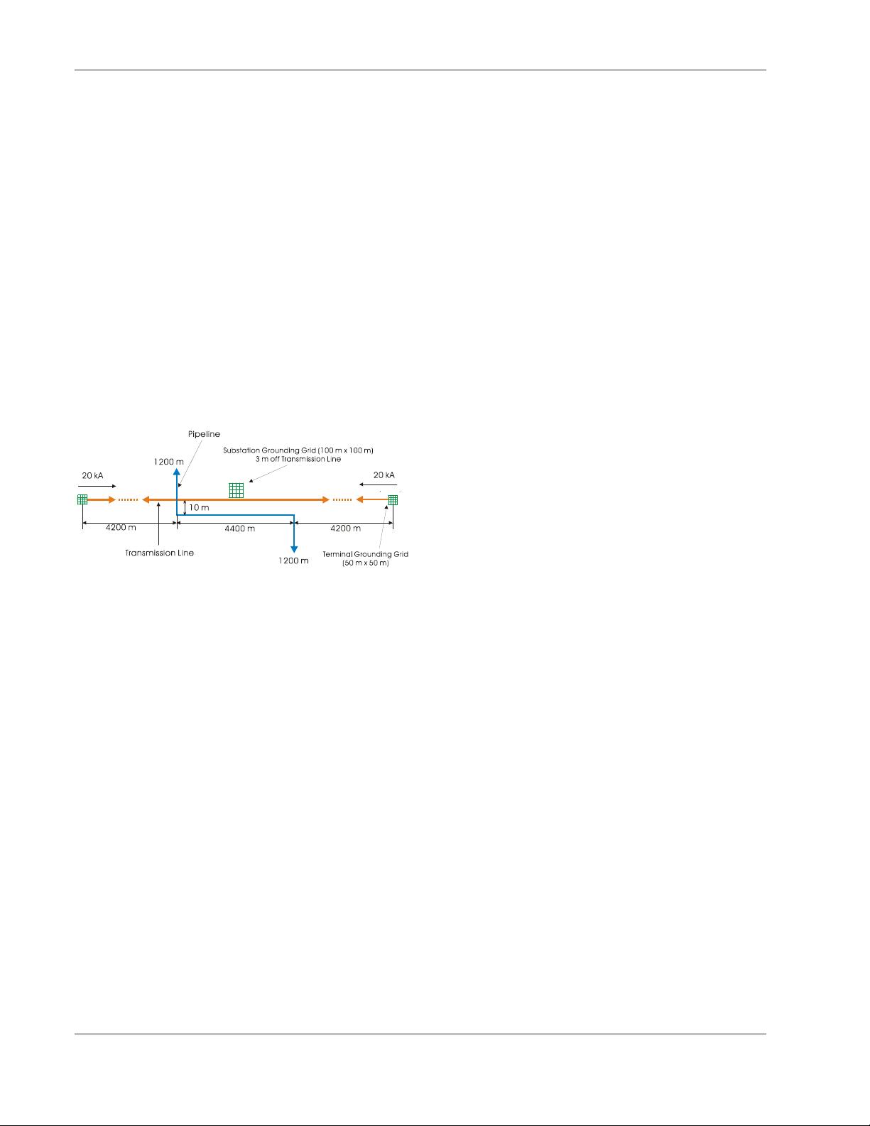
Figure 4-1 shows a typical configuration of a transmission system with a pipeline (refered to as the victim
line in TLC instead of pipeline because it can be a communication line or a rail) parallel to the transmission
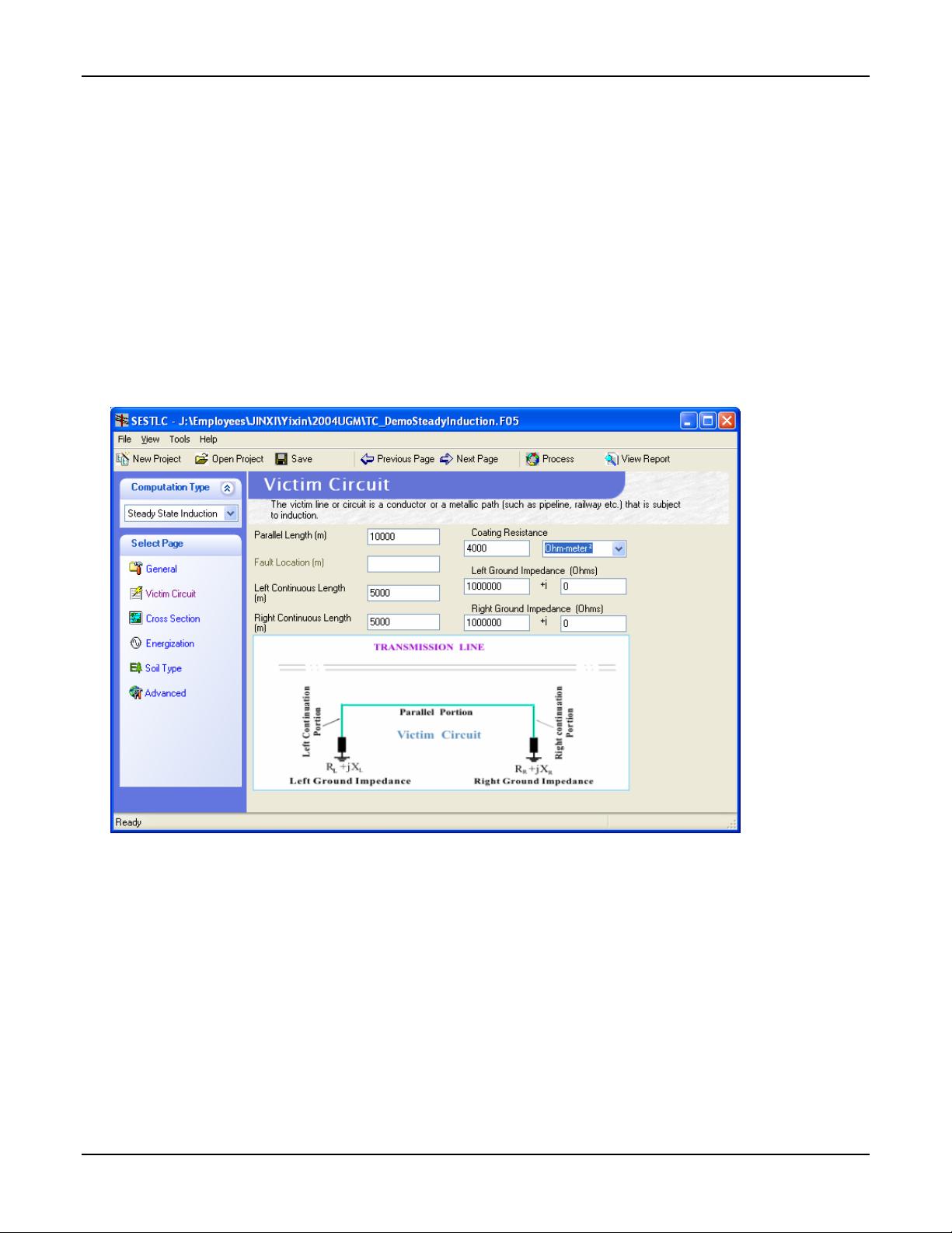
line. The parallel length of the pipeline with the transmission line is 10 km. Both the left and right continuous
lengths are 5 km. The cross section of the transmission line and pipeline configuration is illustrated in Figure
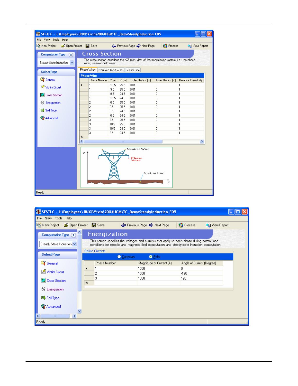
4-2. Each of the phase wires consists of four solid copper conductors bundled together in a rectangular shape.
The conductor radius is 0.01 meter, and the size of the rectangle is 1 meter by 1 meter. The cross section and
physical dimensions of the transmission line are shown in Figure 4-2.
Figure 4-1 A Typical Transmission Line System with Pipeline.