没有合适的资源?快使用搜索试试~ 我知道了~
carsim-help
资源推荐
资源详情
资源评论
Mechanical Simulation VehicleSim Products
755 Phoenix Drive, Ann Arbor MI, 48108, USA
Phone: 734 668-2930 • Fax: 734 668-2877 • Email: info@carsim.com carsim.com
1 / 66 December 2018
Paths and Road Surfaces
Reference Paths ...................................................................................................... 2
ID Numbers...................................................................................................... 3
Coordinate Transformations ............................................................................ 4
The LTARG Configurable Function ................................................................ 5
Using VS Reference Paths ............................................................................... 7
The Path Segment Builder Screen ................................................................... 9
The Path/Road Segment Builder (Legacy) Screen ........................................ 15
Path and Road Tables with X-Y Coordinates ................................................ 17
Working with GPS Data ................................................................................ 22
Smoothing Path Data ..................................................................................... 23
Road Surface Physical Properties ......................................................................... 24
Using Road Surfaces ...................................................................................... 25
The Road: 3D Surface Screen ........................................................................ 26
Road Elevation Screens ................................................................................. 33
Road Friction Screens .................................................................................... 39
The Paths and Roads Segment Builder (Legacy) Screen ............................... 39
Path and Road Tables with X-Y Coordinates ................................................ 44
Connecting Road Surfaces ................................................................................... 46
Points of Interest for Boundaries ................................................................... 47
Boundary Definitions ..................................................................................... 47
The Road Boundaries Screen ......................................................................... 49
Guidelines for Setting Road Boundaries ........................................................ 54
Initial Vehicle Location and Orientation .............................................................. 58
Horizontal Position and Yaw Angle .............................................................. 58
Vertical Position and Orientation of the Lead Sprung Mass ......................... 59
Initial Road Surface ....................................................................................... 60
Roughness Profiles ............................................................................................... 61
Profile Measurement ...................................................................................... 61
The Surface Roughness Profiles Screen ........................................................ 62
Vehicle-Road Axis System .................................................................................. 65
References ............................................................................................................ 66
BikeSim, CarSim, and TruckSim include 3D multibody models that simulate vehicle dynamics
under driver/rider control on a 3D ground surface. The equations of motion for the physics math
models are formulated using global X-Y-Z coordinates; all positions, velocities, and accelerations
are available in global coordinates, and sometimes, local body-fixed coordinate systems.
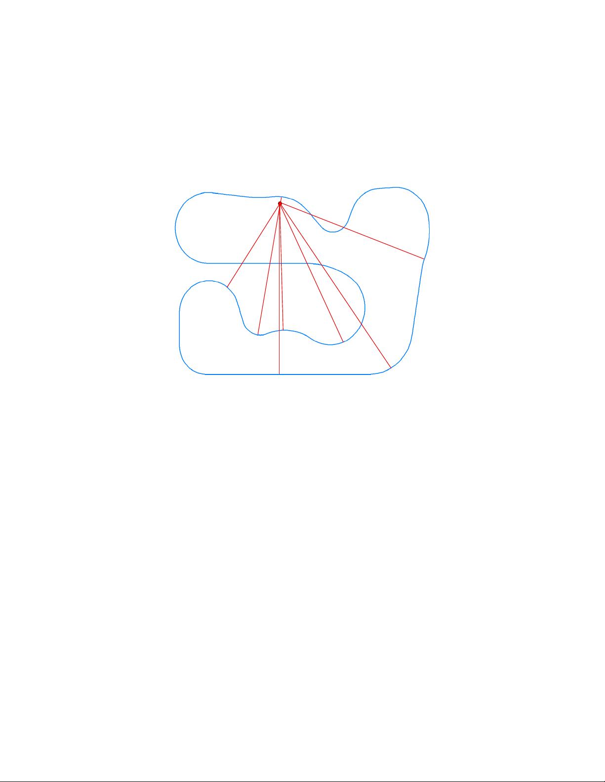
In most simulations, the vehicle is controlled to follow paths of interest, and tires only contact the
ground near those paths of interest. In the VehicleSim math model, the concept of a road surface
is mainly a representation of the ground properties (geometry and friction) in a form that is well-
defined where the vehicle tires are likely to travel, and sparse or nonexistent where the tires are
unlikely to be. To do this, VS Roads represent the road surface using a coordinate system based on
2 / 66
a 2D VS Reference Path — a continuous line that exists in a horizontal plane with continuity in
position and gradient.
In addition to providing the coordinate system for describing road surface properties, VS Reference
Paths are used to define tracking for traffic vehicles and steering controllers.
VehicleSim models support up to 200 reference paths and up to 100 road surfaces. The road
surfaces can be connected to efficiently describe the geometric and friction interface to the vehicle
tires wherever the vehicle is likely to go.
Besides representing roads in the vehicle math model, BikeSim, CarSim, and TruckSim generate
3D shapes to help visualize the road surfaces. Two screens used to determine how a road appears
visually are described in a separate Help document: Road Surface Visualization.
Note Roads and paths in BikeSim, CarSim, and TruckSim are intended for use
by two levels of users. Model Users are engineers and designers who will
be simulating vehicles in previously defined scenarios and conditions. If
the simulation has just one road and mainly involves the evaluation of the
vehicle behavior, it is usually not necessary to assemble an environment
with multiple road surfaces; you can just use the existing road datasets or
make copies and adjust the properties.
The other level of user is the Model Builder. A Model Builder is a more
advanced user who can assemble paths, roads, and other simulation
components to build new scenarios with greater complexity. The road and
path concepts in VehicleSim products support the creation and simulation
of complicated situations.
Reference paths are used to define coordinate systems for roads, as targets
for the driver model for steering and speed control, and to define motions
of objects such as traffic vehicles. Managing some of these options
involves extending the model beyond core vehicle dynamics, and requires
some thought and planning.
Road surfaces provide the interface between the tires and ground, perhaps
the most critical part of the vehicle physics model. The vehicle and other
moving objects can use multiple road surfaces added to the simulation.
Reference Paths
A VS Reference Path is a continuous line that exists in a horizontal plane with continuity in position
and gradient. That is, there are no sharp corners.
The purpose of a reference path is to define a 2D coordinate system for describing locations near a
path of interest. The path coordinates are station S (distance along the path) and lateral coordinate
L (distance a point is from the path, measured on a line that intersects the point and the path, and
is perpendicular to the path at the point of intersection (Figure 1). In this coordinate system, the S
coordinate is based on an axis (the path) that is fixed, but not necessarily straight, while the L
3 / 66
coordinate is based on an axis whose location is variable (it starts from the S location on the path),
and whose direction is variable (perpendicular to the path at S).
Figure 1. S and L are the coordinates of a reference path.
The expectation is that the S coordinate will cover a range of hundreds or thousands of meters,
while the L coordinate typically covers a more limited range such as the width of a road.
Note In the special case where the path follows the global X axis, then S=X and
L=Y. Thus, the S-L convention can revert to the global X-Y coordinate
system for applications where a curved path is not of interest.
The main applications in VS Math Models for the S and L coordinates associated with a path are:
1. Closed-loop steering controllers work by minimizing the absolute value of the L
coordinates of preview points ahead of the vehicle relative to a target path.
2. Objects (traffic vehicles, targets for on-board sensors, etc.) can be located relative to the
path using S and L.
3. Lanes are defined using constant values of L for a Reference Path, or possibly, with the
Configurable Function LTARG that defines L as a function of S.
4. Road surface elevation and friction are defined as functions of S and L for a road reference
path.
A VS Reference Path is a sequence of contiguous segments. For example, the path shown in Figure
1 might be defined with three segments: a straight line going from point 1 to point 2, a circular arc
going from point 2 to point 3, and a straight line starting at point 3.
ID Numbers
There are three kinds of ID numbers that are used when dealing with paths and roads:
1. Automatically-generated index numbers, which start with 1 and increase for each dataset
of a given type used in a simulation.
2. Query ID numbers, which are used to access previous results in some path functions.
3. User ID numbers, which are parameters that exist to support the use of datasets within
multiple simulation scenarios, in which the automatically set index numbers might differ.
4 / 66
Automatically Generated Indexes
VS Solvers use an indexing convention for many parameters and Configurable Functions
associated with parts that are added by users as needed, such as payloads, sensors, moving objects,
etc. Index numbers are automatically set to start with 1 for the first instance and incremented for
each instance as new datasets of the same type are scanned. For example, SPATH_START(2) is
a parameter for the second path that was defined in a simulation.
Query ID Numbers
Some path and road functions include a query ID that enables the function to keep information
about previous results obtained with the function. This is done automatically in the VS Solver for
tires. Each time a path or road function is queried by a tire, any searching begins with the most
previous location. The same is true for moving objects. Some of the functions available for use in
VS Commands include a query ID for the same reason.
User ID Numbers
Paths, road surfaces, and a few Configurable Functions have User ID numbers that help use some
datasets in different simulations in which they are used in different combinations. User IDs are
integers that must be 999 or higher, and exist to identify an instance without regard of when it was
loaded. For example, the parameter PATH_ID(3) is the user ID for the third path defined in a
simulation.
Coordinate Transformations
For a path to be used in a multibody physics math model, it is necessary to be able to perform two
types of coordinate transformations:
1. calculate X and Y for a point given S and L, and
2. calculate S and L for a point given X and Y.
Transforming S-L to X-Y
Transforming from S-L to X-Y is accomplished with a direct sequence of calculations (no iteration
required) for all segment types used in VS Reference Paths. Transformations of this sort are
primarily used to locate and orient moving objects and sometimes to locate and orient the vehicle
for initial conditions.
Transforming X-Y to S-L
Transforming from X-Y to S-L is needed to determine road properties where the tire/ground
contacts occur, and to determine the relationship between points of interest and a target path for
steering and speed controllers in the vehicle model.
Going from X-Y coordinates to S-L requires an iterative approach because the segment containing
the X-Y pair must first be located. VS Solvers keep track of the segment on which an object is
located and use internal information to quickly locate the correct segment. As noted in the previous
section, each query into a path has an associated query ID, such that when query is repeated at the
next time step, the software will start searching at the previous location associated with the internal
query ID.
5 / 66
A significant complication arises when there are multiple pairs of S-L coordinates that would be
valid for a single point of interest. For example, Figure 2 shows an aerial view of a racetrack
reference path (blue) and a red point of interest. Any of the points labeled A through I on the
reference path are related to the point of interest with a line perpendicular to the reference path and
therefore yield different, but valid, S-L coordinates for that point, where S is the position on the
path and L is the signed length of the perpendicular line. In this case, point A is probably the desired
location on the path.
Figure 2. Multiple locations on a reference path can provide valid S-L coordinates for a point of
interest.
The internal query IDs usually resolve the ambiguity in S-L coordinate calculations. For example,
suppose that the point of interest shown in Figure 2 is for a point of contact for the left-front tire of
the simulated vehicle. When the S-L coordinates were calculated the previous time step, the point
was very close to point A, and that station value would be the starting S coordinate used for
computing the X-Y to S-L coordinate transformation. This resolves the ambiguity (in most
reasonable cases) and reduces the number of iterations required to compute the S-L transformation.
The LTARG Configurable Function
BikeSim, CarSim, and TruckSim include a Configurable Function LTARG that calculates a lateral
offset L as a function of station S. This function was originally provided to define a target path for
the closed-loop path-follower models, to easily define lane changes and other targets that were
based on a reference path. The LTARG function is also used to control the motions of moving
objects, also relative to a reference path, to represent traffic vehicles, lane markings, and other
features of interest. When used in a VS Command, the function has the form LTARG(0,S,ID)
where 0 is a placeholder, S is station and ID is an automatically generated index between 1 and
200, inclusive. (To use a user ID, the function has the form LTARG(0,S,GET_ILTARG(UID)),
where UID is the user ID.)
When specifying information for the function (a constant, a table of S-L values, etc.), set the system
index parameter ILTARG to the dataset number (ID) of interest.
Point of interest
A
B
C
D
F
H
G
E
I
剩余65页未读,继续阅读
资源评论
CScodemini
- 粉丝: 174
- 资源: 1
上传资源 快速赚钱
- 我的内容管理 展开
- 我的资源 快来上传第一个资源
- 我的收益 登录查看自己的收益
- 我的积分 登录查看自己的积分
- 我的C币 登录后查看C币余额
- 我的收藏
- 我的下载
- 下载帮助
最新资源
- 基于python实现的,利用树莓派的GPIO端口控制输出汉字到点阵LED屏上
- 基于Solidworks、Matlab Simulink、COMSOL的倒立摆协同仿真资料
- 单片机电子设计项目参考资料基于PLL信号发生器的设计论文资料(仅论文)
- 16957123401091706567347925721090.zip
- 汇编语言实现对加密的字符串进行解密
- 基于WebGIS的地图发布系统设计与实现
- Java基于遗传算法的自动排课系统源码.zip
- 单片机电子设计项目参考资料基于IGBT的变频电源设计论文资料(仅论文)
- 单片机电子设计项目参考资料基于GSM短信模块的家庭防盗报警系统论文资料(仅论文)
- tensorflow-1.5.0-cp27-cp27m-win-amd64.whl
资源上传下载、课程学习等过程中有任何疑问或建议,欢迎提出宝贵意见哦~我们会及时处理!
点击此处反馈
安全验证
文档复制为VIP权益,开通VIP直接复制
信息提交成功