没有合适的资源?快使用搜索试试~ 我知道了~
McPATAlpha_TechRep.pdf
需积分: 4 3 下载量 32 浏览量
2020-12-08
23:25:20
上传
评论
收藏 443KB PDF 举报
温馨提示
试读
40页
Soc设计 功耗面积仿真,很详细 精典 Soc设计 功耗面积仿真,很详细 精典 Soc设计 功耗面积仿真,很详细 精典
资源推荐
资源详情
资源评论
McPAT 1.0: An Integrated Power, Area, and Timing Modeling Framework for
Multicore Architectures
∗
Sheng Li
†‡
, Jung Ho Ahn
§‡
, Jay B. Brockman
†
, Norman P. Jouppi
‡
†
University of Notre Dame,
‡
Hewlett-Packard Labs,
§
Seoul National University
†
{sli2, jbb}@nd.edu,
§
gajh@snu.ac.kr,
‡
norm.jouppi@hp.com
Abstract
This paper introduces McPAT 1.0, an integrated power, area, and timing modeling framework that supports com-
prehensive design space exploration for multicore and manycore processor configurations ranging from 90nm to 22nm
and beyond. At the microarchitectural level, McPAT includes models for the fundamental components of a chip mul-
tiprocessor, including in-order and out-of-order processor cores, networks-on-chip, shared caches, integrated memory
controllers, and multiple-domain clocking. At the circuit and technology levels, McPAT supports critical-path timing
modeling, area modeling, and dynamic, short-circuit, and leakage power modeling for each of the device types forecast
in the ITRS roadmap including bulk CMOS, SOI, and double-gate transistors. McPAT has a flexible XML interface to
facilitate its use with many performance simulators.
∗
Currently 1.0 beta version is released.
1
Contents
1 Introduction 4
2 McPAT: Overview and Operation 5
3 Integrated and Hierarchical Modeling Framework 7
3.1 Power Modeling . . . . . . . . . . . . . . . . . . . . . . . . . . . . . . . . . . . . . . . . . . . . . . . 7
3.2 Timing Modeling . . . . . . . . . . . . . . . . . . . . . . . . . . . . . . . . . . . . . . . . . . . . . . 9
3.3 Area Modeling . . . . . . . . . . . . . . . . . . . . . . . . . . . . . . . . . . . . . . . . . . . . . . . 10
3.4 Hierarchical Modeling Framework . . . . . . . . . . . . . . . . . . . . . . . . . . . . . . . . . . . . . 10
4 Modeling Power-saving Techniques 11
4.1 P-state modeling . . . . . . . . . . . . . . . . . . . . . . . . . . . . . . . . . . . . . . . . . . . . . . 11
4.2 C-state modeling . . . . . . . . . . . . . . . . . . . . . . . . . . . . . . . . . . . . . . . . . . . . . . 11
4.2.1 Power-saving State Modeling . . . . . . . . . . . . . . . . . . . . . . . . . . . . . . . . . . . 12
4.2.2 Models in Logic and Memory Structures . . . . . . . . . . . . . . . . . . . . . . . . . . . . . 14
5 Architecture Level Modeling 15
5.1 Core . . . . . . . . . . . . . . . . . . . . . . . . . . . . . . . . . . . . . . . . . . . . . . . . . . . . . 16
5.1.1 Instruction Fetch Unit (IFU) . . . . . . . . . . . . . . . . . . . . . . . . . . . . . . . . . . . . 17
5.1.2 Renaming Unit . . . . . . . . . . . . . . . . . . . . . . . . . . . . . . . . . . . . . . . . . . . 18
5.1.2.1 Register Alias Table (RAT) . . . . . . . . . . . . . . . . . . . . . . . . . . . . . . . 19
5.1.2.2 Dependency Check Logic (DCL) . . . . . . . . . . . . . . . . . . . . . . . . . . . . 20
5.1.2.3 Power, Area, and Timing of Renaming Logic . . . . . . . . . . . . . . . . . . . . . . 21
5.1.3 Scheduling Unit and Execution Unit . . . . . . . . . . . . . . . . . . . . . . . . . . . . . . . . 22
5.1.3.1 Reservation Station . . . . . . . . . . . . . . . . . . . . . . . . . . . . . . . . . . . 22
5.1.3.2 Instruction Issue Window . . . . . . . . . . . . . . . . . . . . . . . . . . . . . . . . 23
5.1.3.3 Result Broadcast Bus . . . . . . . . . . . . . . . . . . . . . . . . . . . . . . . . . . 23
5.1.3.4 Reorder Buffer (ROB) . . . . . . . . . . . . . . . . . . . . . . . . . . . . . . . . . . 24
5.1.4 Execution Unit . . . . . . . . . . . . . . . . . . . . . . . . . . . . . . . . . . . . . . . . . . . 24
5.1.4.1 Register Files . . . . . . . . . . . . . . . . . . . . . . . . . . . . . . . . . . . . . . 24
5.1.5 Memory Management Unit . . . . . . . . . . . . . . . . . . . . . . . . . . . . . . . . . . . . . 25
5.1.6 Load and Store Unit . . . . . . . . . . . . . . . . . . . . . . . . . . . . . . . . . . . . . . . . 25
5.1.7 Pipeline Logic . . . . . . . . . . . . . . . . . . . . . . . . . . . . . . . . . . . . . . . . . . . 26
5.1.8 Undifferentiated core . . . . . . . . . . . . . . . . . . . . . . . . . . . . . . . . . . . . . . . . 26
5.1.9 Models of Multithreaded Processors . . . . . . . . . . . . . . . . . . . . . . . . . . . . . . . . 27
5.2 Network on Chip (NoC) . . . . . . . . . . . . . . . . . . . . . . . . . . . . . . . . . . . . . . . . . . 27
5.2.1 Routers . . . . . . . . . . . . . . . . . . . . . . . . . . . . . . . . . . . . . . . . . . . . . . . 28
5.2.1.1 Flit Buffer . . . . . . . . . . . . . . . . . . . . . . . . . . . . . . . . . . . . . . . . 29
5.2.1.2 Arbiter and Allocator . . . . . . . . . . . . . . . . . . . . . . . . . . . . . . . . . . 29
5.2.1.3 Crossbar . . . . . . . . . . . . . . . . . . . . . . . . . . . . . . . . . . . . . . . . . 30
5.2.2 Inter-router Link . . . . . . . . . . . . . . . . . . . . . . . . . . . . . . . . . . . . . . . . . . 31
2
5.3 On-chip Caches . . . . . . . . . . . . . . . . . . . . . . . . . . . . . . . . . . . . . . . . . . . . . . . 31
5.4 Memory controller . . . . . . . . . . . . . . . . . . . . . . . . . . . . . . . . . . . . . . . . . . . . . 32
5.4.1 Front-end engine . . . . . . . . . . . . . . . . . . . . . . . . . . . . . . . . . . . . . . . . . . 32
5.4.2 Transaction processing engine and PHY . . . . . . . . . . . . . . . . . . . . . . . . . . . . . . 32
5.5 Clocking . . . . . . . . . . . . . . . . . . . . . . . . . . . . . . . . . . . . . . . . . . . . . . . . . . . 32
6 Circuit Level Modeling 32
6.1 Hierarchical repeated wires . . . . . . . . . . . . . . . . . . . . . . . . . . . . . . . . . . . . . . . . . 32
6.2 Arrays . . . . . . . . . . . . . . . . . . . . . . . . . . . . . . . . . . . . . . . . . . . . . . . . . . . . 34
6.3 Logic . . . . . . . . . . . . . . . . . . . . . . . . . . . . . . . . . . . . . . . . . . . . . . . . . . . . 34
6.4 Clock distribution network . . . . . . . . . . . . . . . . . . . . . . . . . . . . . . . . . . . . . . . . . 34
7 Technology Level Modeling 35
8 Validation 35
3
1 Introduction
Power dissipation, and the resulting heat issues, have become possibly the most critical design constraint of modern
and future processors. This concern only grows as the semiconductor industry continues to provide more transistors per
chip in pace with Moore’s Law. Industry has already shifted gears to deploy architectures with multiple cores [31, 45],
multiple threads [25, 28], and large last-level caches [31, 45] so that processors can be clocked at a lower frequency and
burn less power, while still getting better overall performance. Controlling power and temperature in future multi-core
and many-core processors will require even more novel architectural approaches.
Area remains one of the key design constraints to keep the cost of designs under control because die costs are
proportional to the second power of the area [18]. At very small feature sizes, little margin exists between design rules
and manufacturing process variations, leading to an average 5% decrease in expected die yield with each successive
technology node for mature IC designs [49]. Therefore, on-chip resources including cores and interconnects must be
carefully designed to achieve good trade-offs between performance and cost.
Power, area, and timing need to be studied together more than ever as technology keeps scaling down. However,
our ability to propose, design, and evaluate new architectures for this purpose will ultimately be limited by the quality
of tools used to measure the effects of these changes. Accurately modeling these effects also becomes more difficult
as we push the limits of technology. Future multi/manycore designs drive the need for new tools to address changes in
architecture and technology. This includes the need to accurately model multicore and manycore architectures, the need
to evaluate power, area, and timing simultaneously, the need to accurately model all sources of power dissipation, and
the need to accurately scale circuit models into deep-submicron technologies.
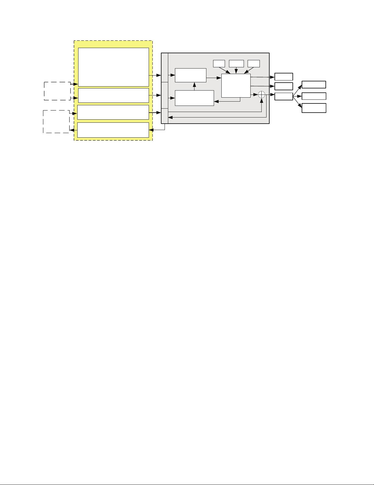
This report introduces a new power, area, and timing modeling framework called McPAT (Multicore Power, Area,
and Timing), which addresses these challenges. McPAT advances the state-of-the-art of processor modeling in several
directions. First, McPAT is an integrated power, area, and timing framework that enables architects to use new metrics
combining performance with both power and area such as energy-delay-area product (EDAP), which are useful to
quantify the cost of new architectural ideas. McPAT specifies the low-level design parameters of regular components
(interconnects, caches, other array-based structures, etc.) based on high-level constraints (clock rate and optimization
target) given by a user, ensuring that the user is always modeling a reasonable design. This approach enables the user, if
they choose, to ignore many of the low-level details of the components being modeled.
Second, McPAT models not just dynamic power but also static and short-circuit power. This is critical in deep-
submicron technologies since static power has become comparable to dynamic power [27, 50]. By modeling all three
types of power dissipation, McPAT gives a complete view of the power envelope of multicore processors.
Third, McPAT provides a comprehensive solution for multithreaded and multicore/manycore processor power. Con-
temporary multicores are complex systems of cores, caches, interconnects, memory controllers, multiple-domain clock-
ing, etc. McPAT models the power of the important components of multicore processors, including all the components
listed above. McPAT supports detailed and realistic models that are based on existing OOO (out-of-order) processors.
McPAT can model both a reservation-station-model and a physical-register-file model based on real architectures, in-
cluding the Intel P6 [22] and Netburst [19].
Fourth, McPAT handles technologies that can no longer be modeled by linear scaling assumptions. The simple
linear scaling principles are no longer valid because device scaling has become highly non-linear in the deep-submicron
era. McPAT provides an integrated solution that models all the power sources. Our power-modeling tool makes use of
technology projections from ITRS [50] for dynamic, static, and short-circuit power; as a result, this tool will naturally
evolve with ITRS even beyond the end of the current road map.
4
Chip
Representation
Optimizer
Timing
Area
Stats Configure
MCPAT
Power/Area/
Timing Model
Arch. Circuit Tech.
Power
Dynamic
Leakage
Short-circuit
XML Interface
Optimization
(Micro)Architecture Param
Frequency, Vdd, In-order,
OoO, Cache Size NoC type
Core count, Multithreaded? …
Circuit Parameters
SRAM, DRAM, DFF, Crossbar type ...
Tech Parameters
Device (HP, LSTP, LOP) , Wire Type
Optimization Target
Max area/power Deviation
Optimization function
Machine Stats
Hardware utilization
P-State / C-state Config
Runtime Power Stats
Thermal Stats
If thermal Model plugged in
User Input
Cycle-by-cycle
performance
simulator
Figure 1: Block diagram of the McPAT framework.
2 McPAT: Overview and Operation
McPAT is the first integrated power, area, and timing modeling framework for multithreaded and multicore/manycore
processors. It is designed to work with a variety of processor performance simulators (and thermal simulators, etc.) over
a large range of technology generations. McPAT allows a user to specify low-level configuration details. It also provides
default values when the user decides to specify only high-level architectural parameters.
Figure 1 is a block diagram of the McPAT framework. Rather than being hardwired to a particular simulator, McPAT
uses an XML-based interface with the performance simulator. McPAT uses an XML parser [23] developed by Berghen
et.al to parse the large XML interface file. This interface allows both the specification of the static microarchitecture
configuration parameters and the passing of dynamic activity statistics generated by the performance simulator. McPAT
can also send runtime power dissipation results back to the performance simulator through the XML-based interface, so
that the performance simulator can react to power or even temperature data. This approach makes McPAT very flexible
and easily ported to other performance simulators. Since McPAT provides complete hierarchical models from the
architecture to technology level, the XML interface also contains circuit implementation style and technology parameters
that are specific to a particular target processor. Examples are array types, crossbar types, and CMOS technology
generations with associated voltage and device types.
The key components of McPAT are (1) the hierarchical power, area, and timing models, (2) the optimizer for de-
termining circuit level implementations, and (3) the internal chip representation that drives the analysis of power, area,
and timing. Most of the parameters in the internal chip representation, such as cache capacity and core issue width, are
directly set by the input parameters.
McPAT’s hierarchical structure allows it to model structures at a low level including underlying device technology,
and yet still allows an architect to focus on a high-level architectural configuration. The optimizer determines missing
parameters in the internal chip representation. McPAT’s optimizer focuses on two major regular structures: interconnects
and arrays. For example, the user can specify the frequency and bisection bandwidth of on-chip interconnects or the
capacity, associativity, the number of cache banks, while letting the tool determine the implementation details such as
the choice of metal planes, the effective signal wiring pitch for the interconnect, or the length of wordlines and bitlines of
the cache bank. These optimizations lessen the burden on the architect to figure out every detail, and significantly lowers
the learning curve to use the tool. Users always have the flexibility to turn off these features and set the circuit-level
implementation parameters by themselves.
5
剩余39页未读,继续阅读
资源评论
Aprilzww
- 粉丝: 0
- 资源: 3
上传资源 快速赚钱
- 我的内容管理 展开
- 我的资源 快来上传第一个资源
- 我的收益 登录查看自己的收益
- 我的积分 登录查看自己的积分
- 我的C币 登录后查看C币余额
- 我的收藏
- 我的下载
- 下载帮助
安全验证
文档复制为VIP权益,开通VIP直接复制
信息提交成功