33
33
3
Digital RDigital R
Digital RDigital R
Digital R
eceiver Handbook:eceiver Handbook:
eceiver Handbook:eceiver Handbook:
eceiver Handbook:
Basics of Software RBasics of Software R
Basics of Software RBasics of Software R
Basics of Software R
adioadio
adioadio
adio
PP
PP
P
entek, Inc.entek, Inc.
entek, Inc.entek, Inc.
entek, Inc. • One Park Way, Upper Saddle River, NJ 07458 • Tel: (201) 818-5900 • Fax: (201) 818-5904 • Email: digrec@pentek.com • http://www.pentek.com
RF
AMP
LOCAL
OSCILLATOR
DEMODULATION
(Detector)
AUDIO
AMPLIF IER
IF AMPLIFIER
(Narrowband Filter)
ANTENNA
SPEAKER
MIXER
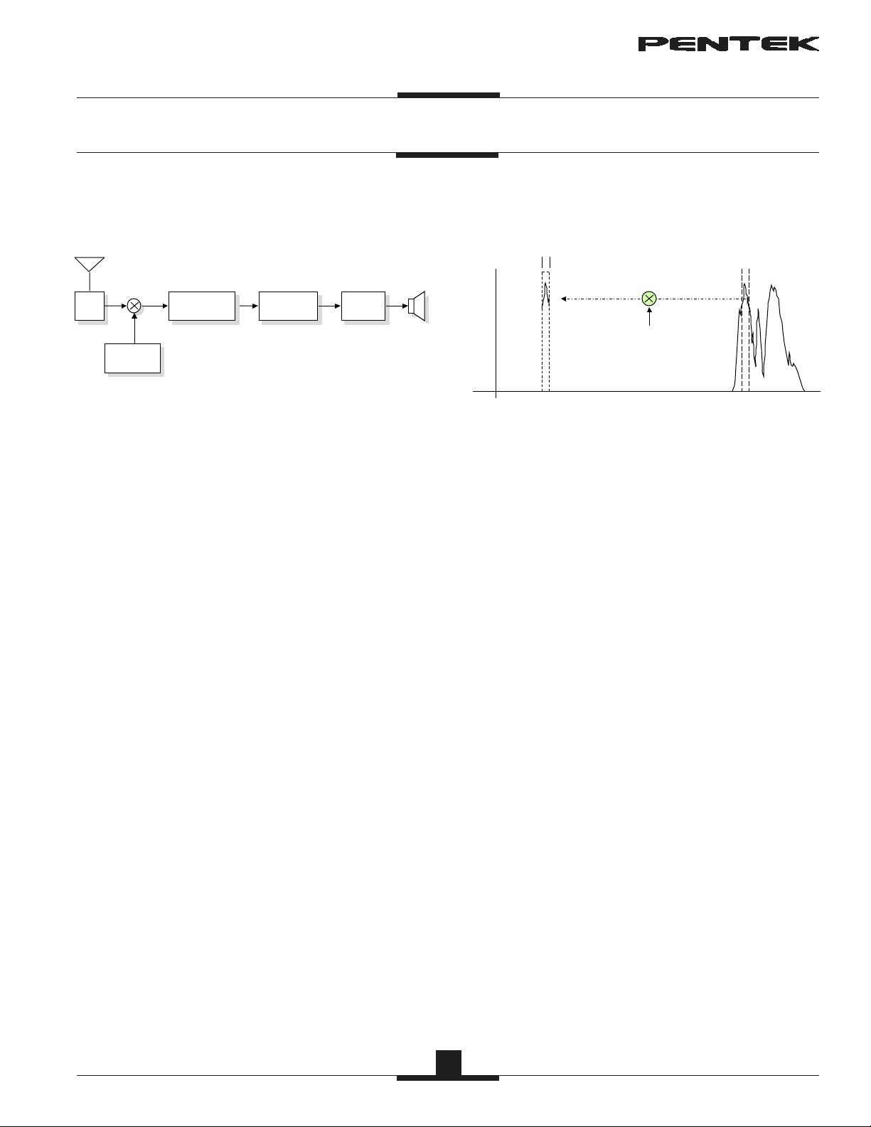
Figure 1
The conventional heterodyne radio receiver as seen
in Figure 1 has been in use for nearly a century. Let’s
review the structure of the analog receiver so comparison
to the digital receiver becomes apparent.
First the RF signal from the antenna is amplified,
typically with a tuned RF stage which amplifies a region
of the frequency band of interest.
This amplified RF signal is then fed into a mixer
stage. The other input to the mixer comes from the local
oscillator whose frequency is controlled by the tuning
knob on the radio.
The mixer translates the desired input signal to the
IF (intermediate frequency). See Figure 2.
The IF stage is a bandpass amplifier which only lets
one signal or radio station through. Common center
frequencies for IF stages are 455 kHz and 10.7 MHz
for commercial AM and FM broadcasts.
The demodulator recovers the original modulating
signal from the IF output using one of several different
schemes.
For example, AM uses an envelope detector and FM
uses a frequency discriminator. In a typical home radio,
the demodulated output is fed to an audio amplifier and
then to a speaker.
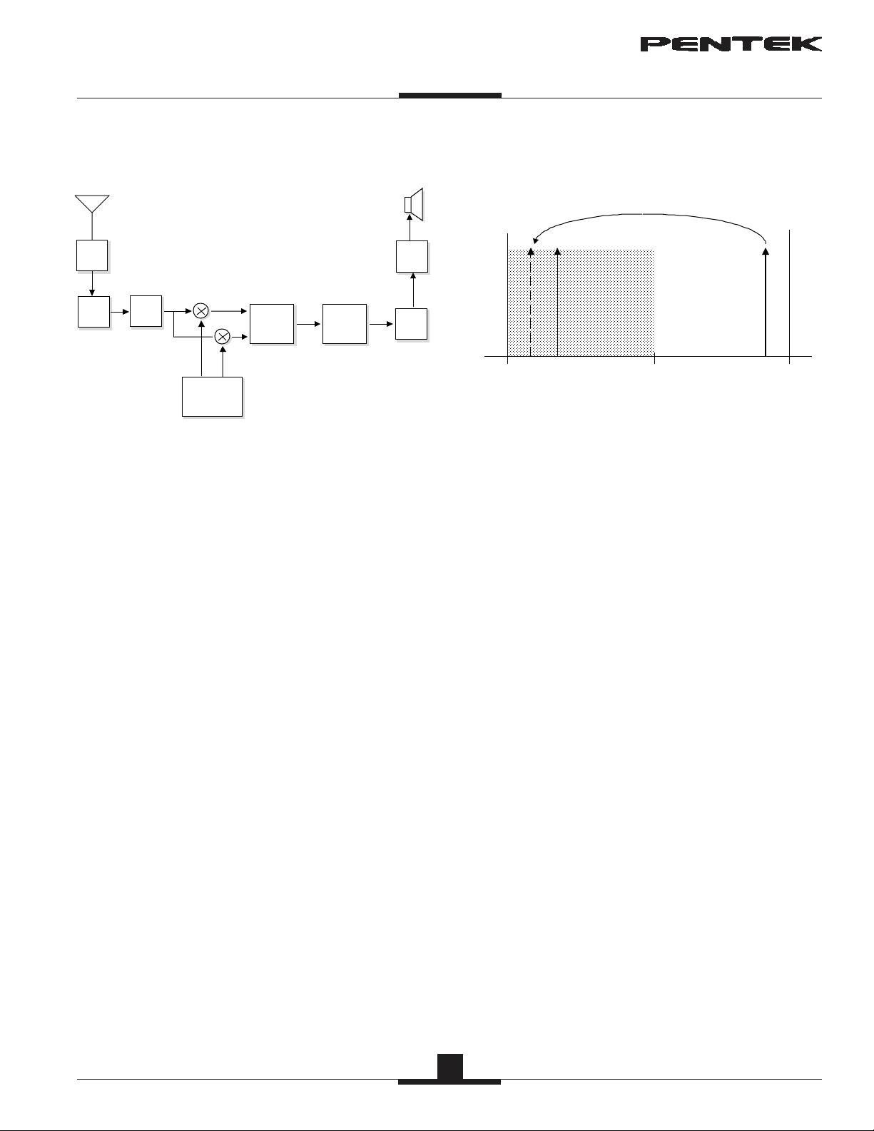
0F
if
F
sig
MIXER TRANSLATES
INPUT SIGNAL BAND
to IF FREQUENCY
LOCAL
OSCILLATOR
F
lo
= F
sig
- F
if
IF BW
Figure 2
Analog RAnalog R
Analog RAnalog R
Analog R
eceiver Block Diagrameceiver Block Diagram
eceiver Block Diagrameceiver Block Diagram
eceiver Block Diagram
Analog RAnalog R
Analog RAnalog R
Analog R
eceiver Mixingeceiver Mixing
eceiver Mixingeceiver Mixing
eceiver Mixing
The mixer performs an analog multiplication of the
two inputs and generates a difference frequency signal.
The frequency of the local oscillator is set so that the
difference between the local oscillator frequency and
desired input signal (the radio station you want to
receive) equals the IF (intermediate frequency).
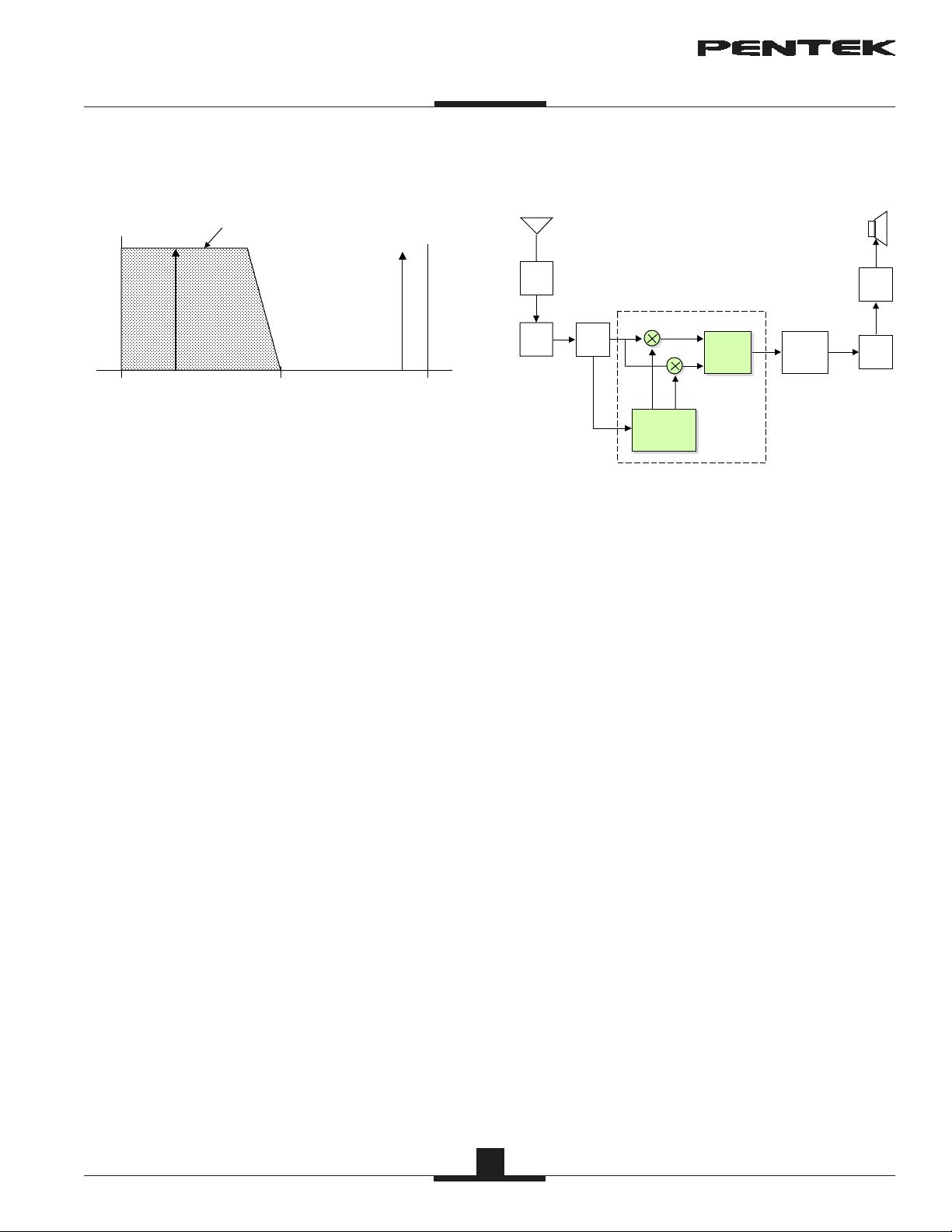
For example, if you wanted to receive an FM
station at 100.7 MHz and the IF frequency is 10.7 MHz,
you would tune the local oscillator to:
100.7 - 10.7 = 90 MHz
This is called “down conversion” or “translating”
since a signal at a high frequency is shifted down to a
lower frequency by the mixer.
The IF stage acts as a narrowband filter which only
passes a “slice” of the translated RF input. The band-
width of the IF stage is equal to the bandwidth of the
signal (or “station”) that you are trying to receive.
For commercial FM, the bandwidth is about 100
kHz and for AM it is about 5 kHz. This is consistent
with channel spacing of 200 kHz and 10 kHz, respectively.
TheorTheor
TheorTheor
Theor
y of Operationy of Operation
y of Operationy of Operation
y of Operation


评论2
最新资源