APS023 Part 2: TX Bandwidth and Power Compensation
© Decawave 2016 This document is confidential and contains information which is proprietary to
Decawave Limited. No reproduction is permitted without prior express written permission of the
author
TABLE OF CONTENTS
1 INTRODUCTION ........................................................................................................................................ 3
1.1 OVERVIEW ................................................................................................................................................. 3
2 WHY DO WE NEED TEMPERATURE COMPENSATION? .............................................................................. 4
2.1 TEMPERATURE EFFECTS ON TRANSMIT POWER AND BANDWIDTH ........................................................................... 4
3 CALIBRATING TX POWER & BANDWIDTH AT MODULE PRODUCTION TEST .............................................. 6
3.1 INTRODUCTION ........................................................................................................................................... 6
3.2 SPECTRUM ANALYSER SETUP .......................................................................................................................... 6
3.3 USING A SPECTRUM MASK ............................................................................................................................. 7
3.4 CALIBRATING BANDWIDTH AND OUTPUT POWER DURING PRODUCT CALIBRATION ..................................................... 8
3.4.1 How to adjust the bandwidth ......................................................................................................... 8
3.4.2 How to adjust the output power ..................................................................................................... 9
3.4.3 Calibrating bandwidth and output power ...................................................................................... 9
3.5 MEASURING TEMPERATURE ........................................................................................................................... 9
3.5.1 Measuring temperature during testing and data collection ........................................................... 9
3.5.2 Measuring temperature during calibration and normal operation ................................................ 9
4 BANDWIDTH COMPENSATION DURING OPERATION .............................................................................. 11
4.1 INTRODUCTION ......................................................................................................................................... 11
4.2 TAKING THE REFERENCE MEASUREMENT ......................................................................................................... 11
4.3 ADJUSTING BANDWIDTH TO COMPENSATE FOR EFFECTS OF TEMPERATURE ............................................................ 12
5 POWER COMPENSATION........................................................................................................................ 15
5.1 INTRODUCTION ......................................................................................................................................... 15
5.2 TAKING THE REFERENCE MEASUREMENT ......................................................................................................... 15
5.3 ADJUSTING OUTPUT POWER TO COMPENSATE FOR THE EFFECTS OF TEMPERATURE .................................................. 15
6 RESULTS ................................................................................................................................................. 16
6.1 OVERVIEW ............................................................................................................................................... 16
6.2 RESULTS DATA ........................................................................................................................................... 16
7 REFERENCES ........................................................................................................................................... 19
8 DOCUMENT HISTORY ............................................................................................................................. 19
9 CHANGE LOG .......................................................................................................................................... 19
10 ABOUT DECAWAVE ............................................................................................................................ 20
LIST OF TABLES
TABLE 1: COMPARISON OF SPECTRUM FOR UNCOMPENSATED AND COMPENSATED MEASUREMENTS AT SELECTED TEMPERATURES ... 18
TABLE 2: TABLE OF REFERENCES .................................................................................................................................. 19
TABLE 3: DOCUMENT HISTORY ..................................................................................................................................... 19
LIST OF FIGURES
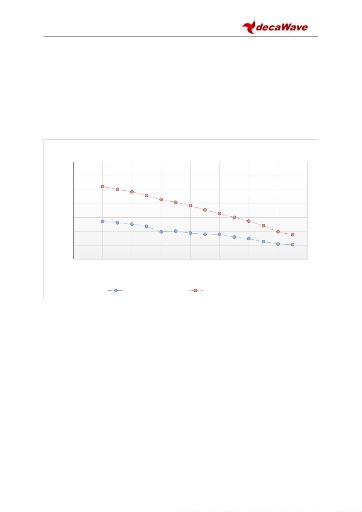
FIGURE 1: CHANNEL POWER MEASURED AT EACH TEMPERATURE (WITHOUT ANY COMPENSATION ............................................... 4
FIGURE 2: BANDWIDTH MEASURED AT EACH TEMPERATURE (WITHOUT ANY COMPENSATION) .................................................... 5
FIGURE 3: SPECTRUM ANALYSER DISPLAYING SPECTRUM FROM DW1000 IN CONTINUOUS FRAME MODE .................................... 7
FIGURE 4: SPECTRUM ANALYSER DISPLAYING SPECTRUM WITH IEEE REGULATORY MASK OVERLAID ............................................. 8
FIGURE 5: FLOWCHART DETAILING THE STEPS TO OBTAIN THE REFERENCE PG_COUNT VALUE ................................................. 12
FIGURE 6: BANDWIDTH CALIBRATION PROCEDURE FLOWCHART .......................................................................................... 14
FIGURE 7: CHANNEL POWER VS TEMPERATURE FOR UNCOMPENSATED (DASHED) AND COMPENSATED MEASUREMENTS ................ 16
FIGURE 8: 10 DB BANDWIDTH VS TEMPERATURE FOR UNCOMPENSATED (DASHED) AND COMPENSATED MEASUREMENTS ............. 17