


CHAPTER 7
FREQUENCY CONVERSION
Nearly all traditional radio receivers,
1
as well as other electronic systems, employ
frequency conversion. This is also called heterodyning and the radio architecture
that uses it is called superheterodyne. Prior to the introduction of the superhetero-
dyne system, selective radios required filters with many variable components, all
changing synchronously to track the signal. With the superheterodyne system,
the desired frequency is converted to a fixed frequency, and the primary filter
can thus be fixed, a much easier and more effective design. Receivers are not the
only applications that use heterodyning to change frequency.
7.1 BASICS
7.1.1 The Mixer
The device in which heterodyning occurs is called a mixer.
2
There are two inputs,
the RF (radio frequency or radio-frequency signal) and the LO (local oscillator).
The desired output is the IF (intermediate frequency or intermediate-frequency
signal). This terminology corresponds well to the mixer’s usage in a receiver,
but we will so identify the mixer’s ports and their signals in other frequency
converters as well.
The mixer contains a device that multiplies the RF signal by the LO signal.
The product of these two sinusoids can be decomposed into a sinusoid whose
frequency is the sum of the RF and LO frequencies and another having the
difference frequency. One of these is the desired frequency-shifted IF.
A simple mixer may consist of a single diode or some other electronic device
(e.g., a field-effect transistor) that can be operated in such a way as to produce
165
Practical RF System Design. William F. Egan
Copyright
2003 John Wiley & Sons, Inc.
ISBN: 0-471-20023-9
166 CHAPTER 7 FREQUENCY CONVERSION
the required product. A general nonlinearity contains a squaring term that will
produce the required product. (We will discuss the mathematics of this process
in the following sections.). When a single diode is used, the RF, LO, and IF
all occur at the same location and can only be separated by filtering. A singly
balanced mixer can be created using two diodes whose inputs a nd outputs are
phased and combined in such a way that one of the inputs (e.g., the LO) cancels
at the IF output port. A doubly balanced mixer (DBM) (Fig. 7.1) can cancel the
appearance of both inputs in the IF. Harmonics of the balanced signals are also
canceled. (The degree of cancellation is finite in all cases.) The remainder of our
discussion assumes a doubly balanced diode mixer but most of the material will
be generally applicable (Egan, 2000, pp. 36–43, 64–67).
Usually the LO power is much greater than the RF power and, as a result,
the mixer acts like a linear element to the through path (RF to IF), except for
the frequency translation. To operate in this manner with large RF signals, the
LO power may have to be increased, perhaps from 7 dBm for a low-level mixer
to as much as 27 dBm for a high-level mixer. High-level mixers may have one
or more additional diodes, or perhaps other passive elements, in series with each
diode shown in Fig. 7.1, or they may combine two of these diode bridges.
Even more complex combinations of diodes and combiners can produce mix-
ers with special advantages. For example, the IF at the sum frequency or at
the difference frequency can be canceled, leaving a single-sideband mixer that
produces an output at only the sum or the difference frequency. At the other
extreme of complexity, LO and mixer are sometimes combined in one active
device, called a converter.
Here are some of the parameters by which mixers are characterized:
Frequency ranges: the RF, LO, and I F ranges for which the mixer is designed.
LO power level: the design or maximum LO power.
Conversion loss: the ratio of IF to RF power, sometimes given as a function of
LO power. This is a lso called single-sideband conversion loss because the
output power of only one of the two converted signals (sum or difference
frequency) is measured.
1-dB input compression level : the RF power at which the conversion loss
increases by 1 dB over the low-level value.
RF
LO
IF
Fig. 7.1 Doubly balanced mixer. RF and LO ports shown are considered balanced but
the IF port is unbalanced.
BASICS 167
Noise figure: this is equal to or greater than the conversion loss.
Spurious levels: a list or table of the levels (usually typical) of various unde-
sired products created in the nonlinearity. These are given for particular
LO and RF power levels and generally are measured with broadband ter-
minations on all ports. They are usually relative to the level of the desired
IF signal.
IM intercept points: usually the IIP3
IM
.
Isolation: between the various ports, LO, RF, and IF; for example, how much
is the LO power attenuated in getting to the IF output.
Impedance and SWR: as for other active devices. The other characteristics
depend on the impedance matches at the terminals.
7.1.2 Conversion in Receivers
Incoming RF signals are injected into a mixer, as is the stronger LO. The nonlin-
earity produces signals at the sum and difference of the LO and RF frequencies,
and one of these becomes the IF, to which the IF filter is tuned. A radio is tuned
by changing the frequency of the LO, and thus of the RF signal that will convert
to the IF frequency. The range of incoming frequencies is restricted by a rela-
tively broad filter, either fixed or tuned. This prevents the sum frequency from
being received when the difference frequency is desired and visa versa. Among
these two inputs, the undesired signal is called the image of the desired signal.
The process is illustrated in Fig. 7.2.
The desired conversion process is indicated by Eq. ( 3.38) or (3.39), which can
be combined to give the tuned frequency as
f
R
=|f
L
± f
I
|.(7.1)
Here the RF frequency that will pass through the IF filter after conversion is given
as a function of the LO frequency. The sign in the equation is controlled by the
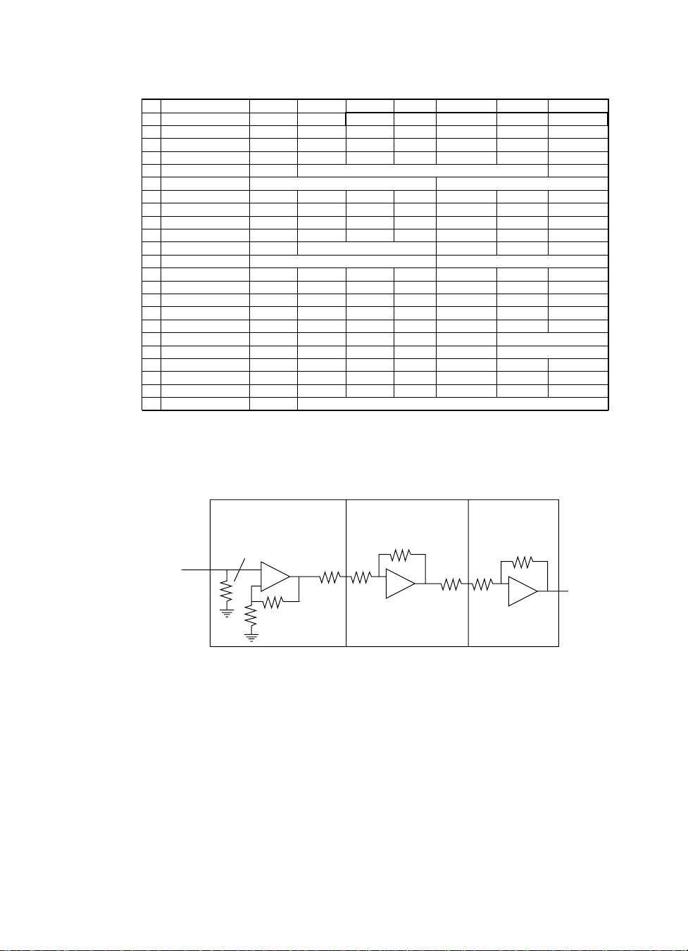
RF in
RF filter
Preamplifier
Mixer
Frequency
selection
Triplexer
Tune oscillator
IF filter
IF
amplifier
Out-of-band
termination
LO
Fig. 7.2 Superheterodyne architecture. The out-of-band termination is good design prac-
tice but not essential. (The upper half of the triplexer is a bandstop filter; the lower half
is a matching bandpass filter.)

168 CHAPTER 7 FREQUENCY CONVERSION
RF filter, which should allow only one of these frequencies to pass — otherwise
both can be received. The process is illustrated in Fig. 3.10. The bandwidths can
be seen there from the width of the noise bands.
Since the sum or difference frequency is normally generated in a nonlinearity,
spurious signals (spurs) at other frequencies are also generated, commonly at
weaker levels. This is the same process that was described in Chapter 4, except
that, here, one of the two significant inputs is the relatively large LO. We do not
want to see either of the inputs in the IF. We are looking for one of the products
of the RF and the LO, produced in the nonlinearity, and are trying to avoid other
products of these two signals and of other, unavoidable, input signals, with the
LO. This involves a more complex design process.
7.1.3 Spurs
When the LO is tuned to produce a signal at the IF frequency according to
Eq. (7.1) with the intended sign, and a signal is produced in the IF, but by a
process that gives a different relationship between the RF a nd IF frequencies, we
say we have a spurious response, or spur. The spur appears to have been converted
from the RF frequency that corresponds, by the equation for the desired response,
to the LO setting; but it is, in fact, the response to some other signal. Spurious
responses to the intended RF signal should be rejected by the IF filter while the
RF filter limits the range of RF frequencies that might otherwise produce spurs.
A designer may say that there is a spur at some frequency, referring either to the
frequency of a n I F signal resulting from a spurious response or to the frequency
of an RF signal that causes a spurious response in the IF. The former might be
produced by the desired signal; the latter by what can be termed an interferer
since it can cause interference w ith the desired signal.
Spurs that only occur when a certain RF frequency, or range of frequencies, is
received, are called single-frequency spurs — IMs require two RF signals. Spurs
that occur without an RF signal are called internal spurs. They are produced by
contaminating signals elsewhere in the receiver.
Single-frequency spurs are described by
f
IF
= mf
LO
+ nf
RF
.(7.2)
These are called m-by-n spurs or |m|-by-|n| spurs. For example, if m =−2and
n = 3, the spur may be called minus-two-by-three or two-by-three (or −2 × 3
or 2 × 3). If no sign is given, it is probably safer to assume it has been left out
rather than to assume that both signs are positive. If we want to specify m = 2
and n = 3, we can say plus-two-by-plus-three. We will put the LO multiplier m
first; sometimes it is done the other way.
3
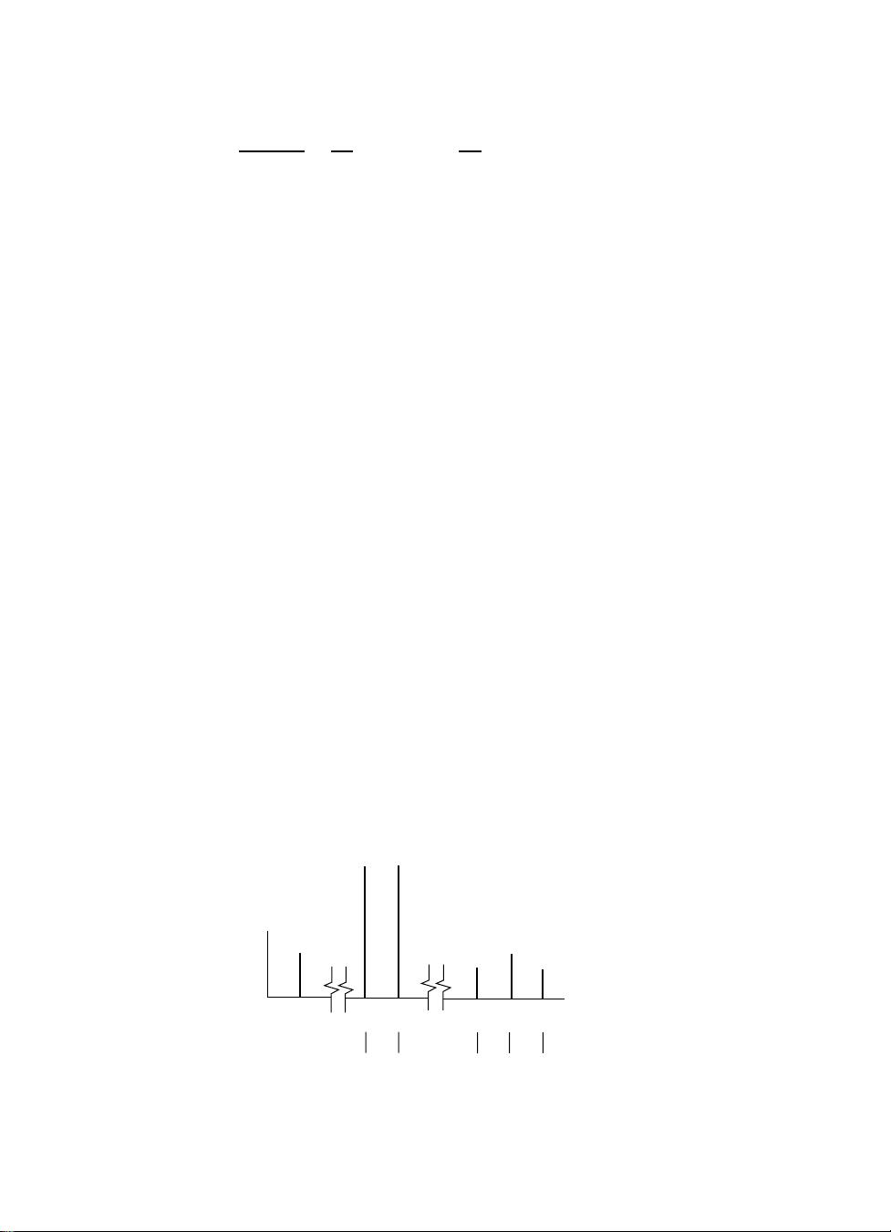
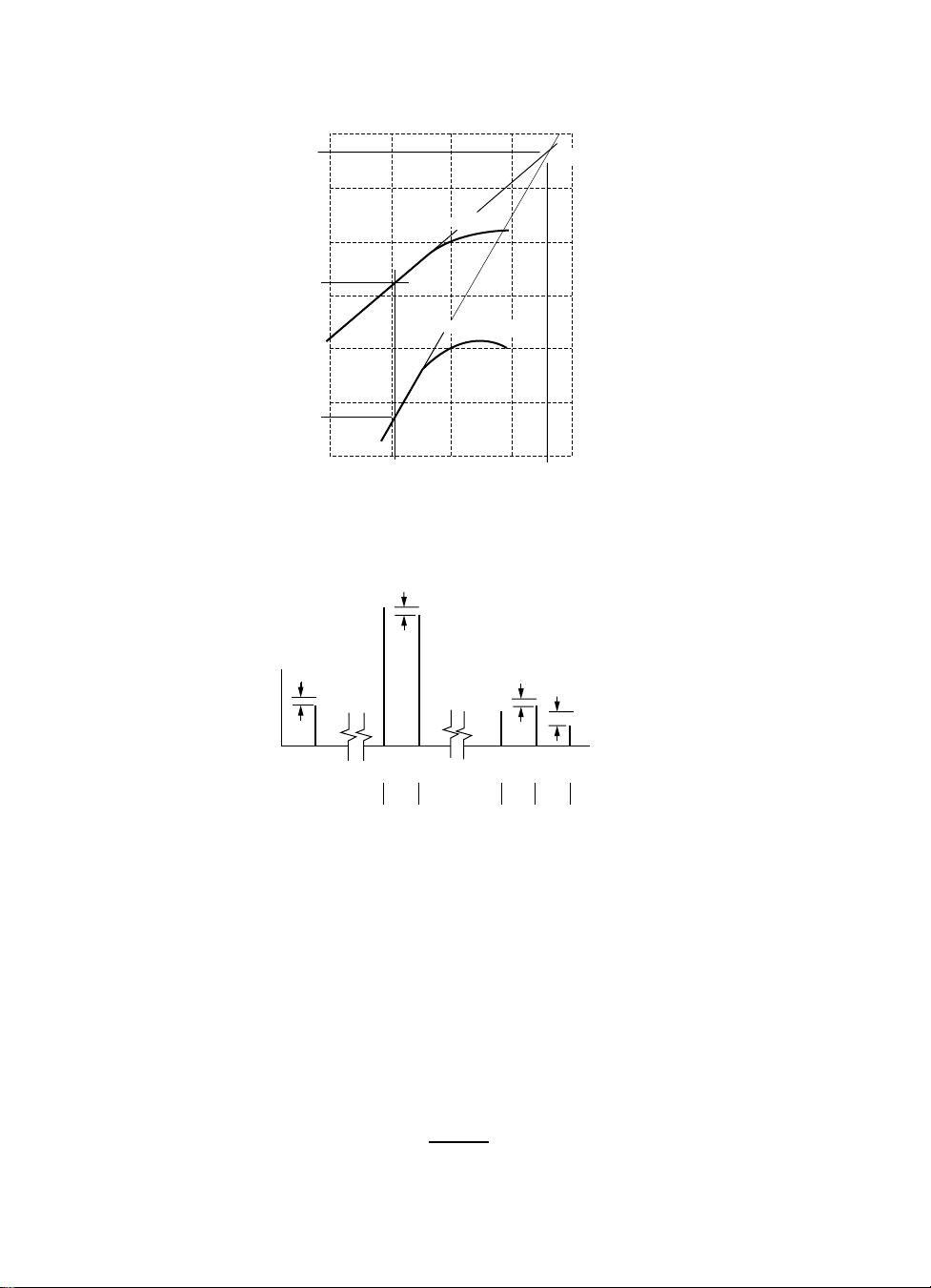
Figure 7.3 is a chart that gives the expected level of various spurious responses.
It is organized as an |n|×|m| matrix of spur levels relative to the level of the
desired 1 × 1 signal. This particular chart is unusual in that it gives information
for three different mixers at two RF power levels and in the large number of
spurs for which it gives values.
7
6
5
4
3
2
1
0
79 > 99 > 99
90 > 99 > 99 86 > 99 > 99 91 > 99 > 99 91 > 99 97 90 > 99 > 99 84 > 99 > 99 93 > 99 > 99 84 > 99 > 99 88 > 99 98
72 93 > 99 70 73 96 71 87 > 99 52 72 95 77 88 > 99 46 66 > 99 75 85 > 99 45 64 90 73 82 > 99
> 90 > 90 > 90 > 90 > 90 > 90 > 90 > 90 > 90 > 90 > 90 > 90 87 > 90 > 90 > 90 > 90 > 90 > 90 > 90 > 90 > 90 > 90 > 90
> 90 > 90 > 90 > 90 > 90 > 90 > 90 > 90 > 90 > 90 > 90 > 90 > 90 > 90 > 90 > 90 > 90 > 90 > 90 > 90 > 90 > 90 > 90 > 90 > 90 > 90 > 90
> 90 > 90 > 90
> 90 > 90 > 90 86 > 90 > 90 88 > 90 > 90 88 > 90 > 90 85 > 90 > 90 86 > 90 > 90 85 > 90 > 90 > 90 > 90 > 90
80 > 90 > 90 > 90 > 90 > 90 71 > 90 > 90 > 90 > 90 > 90 68 > 90 > 90 > 90 > 90 > 90 65 > 90 > 90 88 > 90 > 90
86 > 90 > 90
67 87 > 90 64 77 > 90 69 87 > 90 50 78 > 90 77 > 90 > 90 47 75 > 90 74 85 > 90 44 77 > 90 74 88 > 90
69 79 > 99 80 > 99 > 99 74 78 > 99 83 > 99 > 99
> 90 > 90 90
63 78 > 99 78 > 99 > 99 60 81 > 99 71 90 > 99
80 96 88
79 80 91
51 63 81 49 58 73 53 65 85 51 60 69 55 65 85 48 55 68 54 64 85 53 54 64 58 66 87
82 96 > 99 77 80 92 82 95 90 76 82 95 77 98 87 72 78 94 77 90 87
69 68 64 72 67 71 79 76 62 67 67 70 75 80 63 66 66 70 72 82 61 68 66 62 75 83 64
73 86 73 73 75 83
0 0 0
0 0 0
74 84 75 70 75 79 71 86 80 64 74 80 69 87 77 64 74 82 69 84 79
25 25 24
36 39 29
26 27 18 35 31 10 39 36 23 50 47 14 41 36 19 53 51 17 49 37 21 51 63 19
45 42 20 52 46 32 63 58 24 45 37 29 60 65 27 71 49 30 64 75 29
39 39 35 13 11 11 45 50 42 22 16 19 54 59 50 37 19 39 59 59 49
24 23 24 35 39 34 13 11 11 40 46 42 24 14 18 45 62 49 28 19 37 49 53 49
A B C
A
Class 1 (M1)
0.2 – 250 MHz
LO: 7 dBm
B
Class 2, Type 2 (MID, M9BC)
0.5 – 500 MHz
LO: 17 dBm
C
Class 3 (MIE, M9E)
1 – 400 MHz
LO: 27 dBm
RF: 0 dBm
RF: −10 dBm
n (RF harmonic number)
m (LO harmonic number)
(a)
(b) (c)
012345678
012345678
Fig. 7.3 Spur-level chart for three doubly balanced mixer classes and two signal levels. Relative spur levels are shown at (a). Each rectangle
contains three columns, one for each of the mixer classes shown at (b). Each rectangle contains two rows, one for each of the RF levels shown
at (c). The LO frequency is 50 MHz and the RF frequency is 49 MHz (Cheadle, 1993, p. 485). The higher mixer classes (Henderson, 1993c,
p. 481) have another diode or other passive components in series with the diode in each leg and are designed for increasingly higher LO power
levels. A minus is understood for all of the relative spur levels.
169


评论1
最新资源