


2
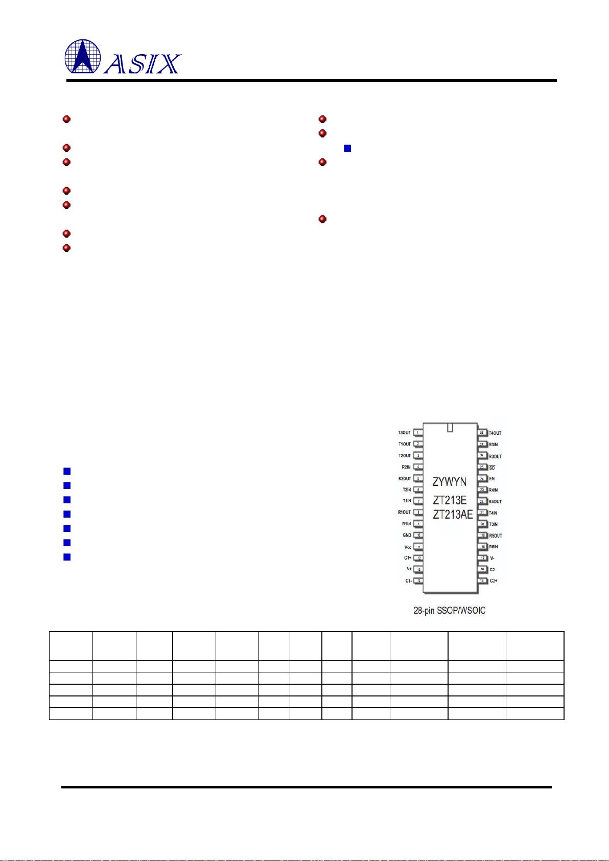
ZT207E/ZT208E/ZT211E/ZT213E/ZT213AE
Low Power 5V 250Kbps RS232 Transceivers
Copyright © 2010-2017 ASIX Electronics Corporation. All rights reserved.
IMPORTANT NOTICE
Copyright © 2010-2017 ASIX Electronics Corporation. All rights reserved.
DISCLAIMER
No part of this document may be reproduced or transmitted in any form or by any means, electronic or mechanical,
including photocopying and recording, for any purpose, without the express written permission of ASIX. ASIX may
make changes to the product specifications and descriptions in this document at any time, without notice.
ASIX provides this document “as is” without warranty of any kind, either expressed or implied, including without
limitation warranties of merchantability, fitness for a particular purpose, and non-infringement.
Designers must not rely on the absence or characteristics of any features or registers marked “reserved”, “undefined”
or “NC”. ASIX reserves these for future definition and shall have no responsibility whatsoever for conflicts or
incompatibilities arising from future changes to them. Always contact ASIX to get the latest document before starting
a design of ASIX products.
TRADEMARKS
ASIX, the ASIX logo are registered trademarks of ASIX Electronics Corporation. All other trademarks are the
property of their respective owners.

3
ZT207E/ZT208E/ZT211E/ZT213E/ZT213AE
Low Power 5V 250Kbps RS232 Transceivers
Copyright © 2010-2017 ASIX Electronics Corporation. All rights reserved.
General Description
The ZT213E series devices are +5V powered EIA/TIA-232
and
V.28/V.24
communication
interfaces
with
low
power
requirements.
These
transceivers
consist
of
combinations
up to five line drivers, five line receivers and the proprietary
switch-capacitor regulated voltage converters.
The ZT211E
and ZT213E/AE feature a low power shutdown mode which
draws as little current as 1μA typical with receiver outputs tri-
stated and in wake-up.
These devices operate from a single
+5V power supply at the guaranteed data rate of 250K bits/sec
with enhanced electrostatic discharge (ESD) protection in all
RS232 I/O pins exceeding ±15KV HBM.
Applications
• Battery-Powered Applications
• Notebooks, Subnotebooks, and Palmtops
• Industrial and Embedded PCs
• Data Cables for Cell Phones and PDAs
• Terminal Adapters and POS terminals
• Peripherals interface
• Routers and HUBs
Features
• Meets EIA/TIA-232F and CCITT V.28/V.24
specifications
for
V
CC
at
+5V
±10%
• Low Quiescent Current – 3mA.
• Low Shutdown Current (where applicable) -
1μA typical, 10μA max.
• Guaranteed Standard Data Rate 250Kbps
• Proprietary Switch-Capacitor Regulated Voltage
Converters (patent pending)
• Wake Up Feature in Shutdown Mode
• Tri-State Receiver Outputs
• Latch-up Free
• ESD Protection for RS-232 I/O's
±15KV Human Body Model (HBM)
• Drop-in Replacements for MAX207E, SP207E,
MAX208E, SP208E, MAX211E, SP211E,
MAX213E, SP213E, ADM213, HIN213, SP213A
• High Data Rate at 1000Kbps Available on ZT213F
Series
Part
Number
# of
RS232
Tx
# of
RS232
Rx
# of Rx
active in
SD
# of
0.1 μF
caps
ShutDown
Wake Up
TTL
Tri-State
Data Rate
(Kbps)
ESD HBM
on RS232
I/O
Pin-to-Pin
Cross
EXAR
Pin-to-Pin
Cross
MAXIM
ZT207E
5
3
0
4
No
No
No
250
± 15KV
SP207E
MAX207E
ZT208E
4
4
0
4
No
No
No
250
± 15KV
SP208E
MAX208E
ZT211E
4
5
0
4
Yes
No
Yes
250
± 15KV
SP211E
MAX211E
ZT213E
4
5
2
4
Yes
Yes
Yes
250
± 15KV
SP213E
MAX213E
ZT213AE
4
5
2
4
Yes
Yes
Yes
250
± 15KV
SP213A
MAX213
Product Selection Guide and Cross Reference
4
ZT207E/ZT208E/ZT211E/ZT213E/ZT213AE
Low Power 5V 250Kbps RS232 Transceivers
Copyright © 2010-2017 ASIX Electronics Corporation. All rights reserved.
Storage
Considerations
Storage
in
a
low
humidity
environment
is
preferred.
Large
high
density
plastic
packages
are
moisture
sensitive
and
should be stored in Dry Vapor Barrier Bags. Prior to usage,
the parts should remain bagged and stored below 40°C and
60%RH. If the parts are removed from the bag, they should
be used within 168 hours or stored in an environment at or
below 20%RH. If the above conditions cannot be followed,
the parts should be baked for 12 hours at 125°C in order to
remove moisture prior to soldering. ASIX ships product in
Dry
Vapor
Barrier
Bags
with
a
humidity
indicator
card
and
desiccant
pack.
The
humidity
indicator
should
be
below
30%RH. The MSL of this product is 3.
The
information
furnished
by
ASIX
has
been
carefully
reviewed for accuracy and reliability. Its application or use,
however, is solely the responsibility of the user. No responsibility
of the use of this information become part of the terms and
conditions of any subsequent sales agreement with ASIX.
Specifications are subject to change without the responsibility
for any infringement of patents or other rights of third parties
which may result from its use. No license or proprietary rights
are granted by implication or otherwise under any patent or
patent rights of ASIX Electronics Corporation.
Absolute
Maximum
Ratings
These are stress ratings only and functional operation of
the device at these ratings or any other above those indicated in
the operation sections of the specifications is not implied.
Exposure to absolute maximum rating conditions for extended
periods of time may affect reliability.
Power
Supply,
(V
CC
)...................................
–0.3V
to
+6.0V
V+ ...............................................................
–0.3V to +7.0V
V– ................................................................
+0.3V to –7.0V
|V+| + |V-|
..............................................................
+13.0V
I
CC
(DC
V
CC
or
GND
current)................................
±100mA
Input
Voltages
TxIN, SHUTDOWN, EN ...............................
–0.3V to +6.0V
RxIN........................................................................... ±25V
Output
Voltages
TxOUT ........................................................................ ±12V
RxOUT..............................................
–0.3V
to
(V
CC
+0.3V)
Short-Circuit
Duration
TxOUT .............................................................. Continuous
Operating Temperature.............................. –40°C to +85°C
Storage Temperature............................... –65°C to +150°C
Power Dissipation Per Package
24-pin SSOP (derate 8.00mW/°C above +70°C)…... 640mW
24-pin WSOIC (derate 11.76mW/°C above +70°C)…941mW
28-pin SSOP (derate 9.52mW/°C above +70°C)…… 762mW
28-pin WSOIC (derate 12.50mW/°C above +70°C) ………..1W

5
ZT207E/ZT208E/ZT211E/ZT213E/ZT213AE
Low Power 5V 250Kbps RS232 Transceivers
Copyright © 2010-2017 ASIX Electronics Corporation. All rights reserved.
1 Electrical Characteristics
Unless otherwise stated, VCC = +5.0V, TA = Tmin to Tmax, C1 to C4 = 0.1μF, typical values apply at VCC = +5.0V and TA = 25°C.
Parameter
Condition
Min
Typ
Max
Units
TTL Logic Input
TTL Logic Output
RS-232 Input
RS-232 Output
Charge Pump Pin
Power Pin
T1IN, T2IN, T3IN, T4IN, T5IN, EN
, SD
R1OUT, R2OUT, R3OUT, R4OUT, R5OUT
R1IN, R2IN, R3IN, R4IN, R5IN
T1OUT, T2OUT, T3OUT, T4OUT, T5OUT
C1P, C1N, C2P, C2N
V
CC
, V
GND
, V
DD
, V
SS
See specifications below
Charge Pump Caps
Temp 0°C to +70°C
Temp –40°C to +85°C
V
CC
Voltage Range
C1P, C1N, C2P, C2N
Commercial Grade
Industrial Grade
V
CC
= +5.0V Supply
0.1
0
–40
4.5
0.1
+25
+25
5
1.0
+70
+85
5.5
μF
°C
°C
V
Supply Current Quiescent
Supply Current
Transmitters Loaded
TTL Inputs = V
CC
/GND, RS-232 Input = float, T
A
= 25°C
V
CC
= +5.0V ±10%, No load on transmitter outputs
(ZT207E, 208E, 211E, 213E)
(ZT213AE)
TTL Inputs = V
CC
/GND, RS-232 Inputs = float, T
A
= 25°C
V
CC
= +5.0V, All transmitter outputs loaded with R
L
= 3KΩ
3
5
15
6
10
mA
mA
mA
Supply Current,
SHUTDOWN Enabled
SD = GND, TTL Inputs = V
CC
/GND, T
A
= 25°C
RS-232 Inputs = float, V
CC
= +5.0V
1
10
μA
TTL
LOGIC
Input
Input Threshold Low
Input Threshold High
Input Hysteresis
Input Leakage Current
Input Leakage Current
V
CC
= +5.0V Supply
V
IN
= V
CC
and GND, TxIN, EN
, SD
V
IN
= V
CC
and GND, TxIN
2.4
0.5
±0.01
50
0.8
±1
200
V
V
V
μA
μA
TTL
LOGIC
Output
Output Voltage Low
Output Voltage High
Output Leakage Current
I
OUT
= 1.6mA
I
OUT
= –1.0mA
Receiver Outputs Disabled, V
OUT
= V
CC
or GND,
SD
= GND, EN
= V
CC
V
CC
–0.6
V
CC
–0.1
±0.05
0.4
±10
V
V
μA
Receiver
Input
Input Voltage Range
Input Threshold Low
Input Threshold High
Input Hysteresis
Input Resistance
T
A
=
T
min
–
T
max
T
A
= 25°C, V
CC
= 5.0V
V
CC
= +5.0V Supply
T
A
= 25°C
V
IN
= ±25V, T
A
= 25°C
–25
0.8
3
1.5
0.5
25
2.4
7
V
V
V
V
KΩ
Transmitter
Output
Output Voltage Swing
Output Resistance
Output Short-Circuit Current
Output Leakage Current
R
L
= 3KΩ, All Outputs are loaded, V
CC
= 5.25V
(ZT207E, 208E, 211E, 213E)
(ZT213AE)
V
CC
= V
DD
= V
SS
= GND, V
OUT
= ±2V
V
OUT
= GND
Transmitter Disabled, V
OUT
= ±12V
±5
±5
300
±6
±9
±5
±60
V
V
Ω
mA
μA


