


Grid-Connected PV Array
Pierre Giroux, Gilbert Sybille, Hydro-Quebec Research Institute (IREQ)
Carlos Osorio, Shripad Chandrachood, The Mathworks
Description
Two demos illustrate use of SimPowerSystems for modeling a PV array connected to a utility grid.
PVarray_Grid_IncCondReg_det.mdl is a detailed model of a 100-kW array connected to a 25-
kV grid via a DC-DC boost converter and a three-phase three-level Voltage Source Converter
(VSC). Maximum Power Point Tracking (MPPT) is implemented in the boost converter by means
of a Simulink model using the “Incremental Conductance + Integral Regulator” technique.
PVarray_Grid_PandO_avg.mdl is an average model of a 200-kW array connected to a 25-kV
grid via two DC-DC boost converters and a single three-phase VSC. The MPPT controller based
on the “Perturb and Observe” technique is implemented by means of a MATLAB Function block
that generates embeddable C code.
The detailed model contains:
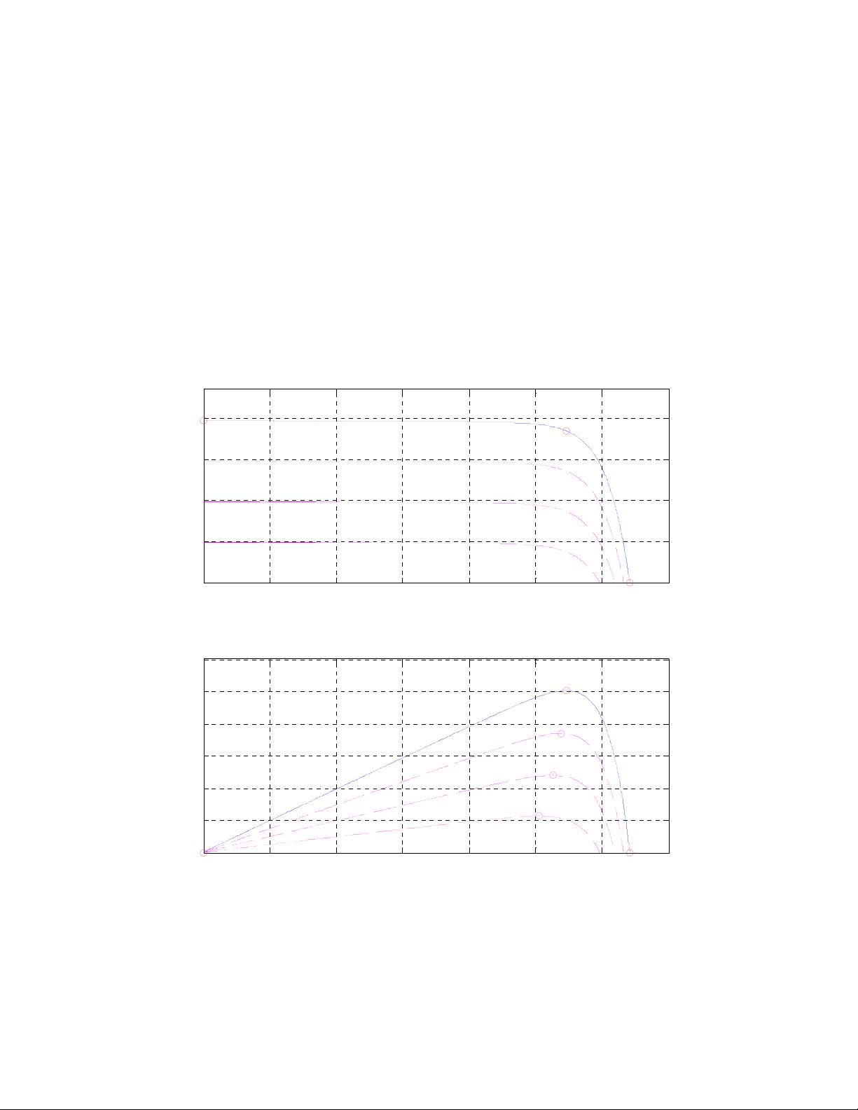
PV array delivering a maximum of 100 kW at 1000 W/m
2
sun irradiance.
5-kHz boost converter (orange blocks) increasing voltage from PV natural voltage (272 V DC at
maximum power) to 500 V DC. Switching duty cycle is optimized by the MPPT controller that
uses the “Incremental Conductance + Integral Regulator” technique.
1980-Hz (33*60) 3-level 3-phase VSC (blue blocks).
The VSC converts the 500 V DC to 260 V AC and keeps unity power factor.
10-kvar capacitor bank filtering harmonics produced by VSC.
100-kVA 260V/25kV three-phase coupling transformer.
Utility grid model (25-kV distribution feeder + 120 kV equivalent transmission system).
For this detailed model, the electrical circuit is discretized at 1 s sample time, whereas sample time used
for the control systems is 100 s.
The average model contains:
Two PV arrays delivering each a maximum of 100 kW at 1000 W/m
2
sun irradiance.
Two average models of boost converter (orange blocks) increasing voltage from PV1 and PV2
voltages to 500 V DC. The two MPPT controllers use the “Perturb and Observe” technique.
Average model of VSC (blue blocks). The VSC converts the 500 V DC to 260 V AC and keeps
unity power factor.
20-kvar capacitor bank filtering harmonics produced by VSC.
200-kVA 260V/25kV three-phase coupling transformer.
Utility grid model (25-kV distribution feeder + 120 kV equivalent transmission system).
In the average model the boost and VSC converters are represented by equivalent voltage sources
generating the AC voltage averaged over one cycle of the switching frequency. Such a model does not
represent harmonics, but the dynamics resulting from control system and power system interaction is
preserved. This model allows using much larger time steps (50 s), resulting in a much faster simulation.
Note that in the average model the two PV-array models contain an algebraic loop. Algebraic loops are
required to get an iterative and accurate solution of the PV models when large sample times are used. These
algebraic loops are easily solved by Simulink.