没有合适的资源?快使用搜索试试~ 我知道了~
Verilog.pdf
资源推荐
资源详情
资源评论
Verilog 1995, 2001, and
SystemVerilog 3.1
Languages for Embedded Systems
Prof. Stephen A. Edwards
Summer 2004
NCTU, Taiwan
The Verilog Language
Originally a modeling language for a very efficient
event-driven digital logic simulator
Later pushed into use as a specification language for logic
synthesis
Now, one of the two most commonly-used languages in
digital hardware design (VHDL is the other)
Virtually every chip (FPGA, ASIC, etc.) is designed in part
using one of these two languages
Combines structural and behavioral modeling styles
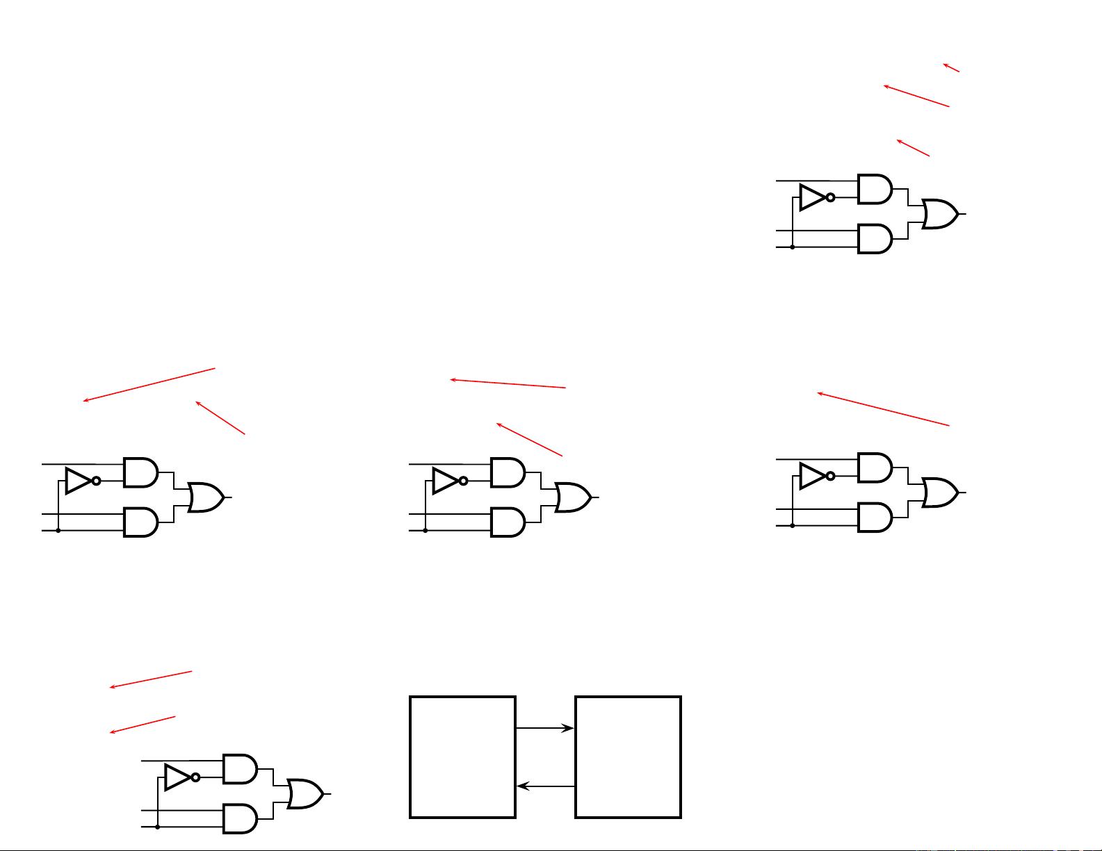
Multiplexer Built From Primitives
module mux(f, a, b, sel);
Verilog programs
built from modules
output f;
input a, b, sel;
Each module has
an interface
and g1(f1, a, nsel),
g2(f2, b, sel);
or g3(f, f1, f2);
not g4(nsel, sel);
Module may contain
structure: instances of
primitives and other
modules
endmodule
g1
g4
g2
g3
a
b
sel
f
nsel
f1
f2
Multiplexer Built with Always
module mux(f, a, b, sel);
output f;
input a, b, sel;
reg f;
always
Modules may
contain one or more
always blocks
@(a or b or sel)
Sensitivity list
contains signals
whose change
makes the block
execute
if (sel) f = a;
else f = b;
endmodule
a
b
sel
f
Multiplexer Built with Always
module mux(f, a, b, sel);
output f;
input a, b, sel;
reg f;
A reg behaves like
memory: holds its value
until imperatively
assigned otherwise
always @(a or b or sel)
if (sel) f = a;
else f = b;
Body of an always block
contains traditional
imperative code
endmodule
a
b
sel
f
Mux with Continuous Assignment
module mux(f, a, b, sel);
output f;
input a, b, sel;
assign
LHS is always set to
the value on the RHS
Any change on the right
causes reevaluation
f = sel ? a : b;
endmodule
a
b
sel
f
Mux with User-Defined Primitive
primitive mux(f, a, b, sel);
output f;
input a, b, sel;
table
1?0 : 1;
Behavior defined using
a truth table that
includes “don’t cares”
0?0 : 0;
?11 : 1;
?01 : 0;
11? : 1;
This is a less pessimistic than
others: when a & b match, sel is
ignored; others produce X
00? : 0;
endtable
endprimitive
a
b
sel
f
How Are Simulators Used?
Testbench generates stimulus and checks response
Coupled to model of the system
Pair is run simultaneously
Testbench
System Model
Stimulus
Response
Result checker
Structural Modeling
When Verilog was first developed (1984) most logic
simulators operated on netlists
Netlist: list of gates and how they’re connected
A natural representation of a digital logic circuit
Not the most convenient way to express test benches
Behavioral Modeling
A much easier way to write testbenches
Also good for more abstract models of circuits
•
Easier to write
•
Simulates faster
More flexible
Provides sequencing
Verilog succeeded in part because it allowed both the
model and the testbench to be described together
How Verilog Is Used
Virtually every ASIC is designed using either Verilog or
VHDL (a similar language)
Behavioral modeling with some structural elements
“Synthesis subset” can be translated using Synopsys’
Design Compiler or others into a netlist
Design written in Verilog
Simulated to death to check functionality
Synthesized (netlist generated)
Static timing analysis to check timing
Two Main Components of Verilog:
Behavioral
Concurrent, event-triggered processes (behavioral)
Initial and Always blocks
Imperative code that can perform standard data
manipulation tasks (assignment, if-then, case)
Processes run until they delay for a period of time or wait
for a triggering event
Two Main Components of Verilog:
Structural
Structure (Plumbing)
Verilog program build from modules with I/O interfaces
Modules may contain instances of other modules
Modules contain local signals, etc.
Module configuration is static and all run concurrently
Two Main Data Types: Nets
Nets represent connections between things
Do not hold their value
Take their value from a driver such as a gate or other
module
Cannot be assigned in an initial or always block
Two Main Data Types: Regs
Regs represent data storage
Behave exactly like memory in a computer
Hold their value until explicitly assigned in an initial or
always block
Never connected to something
Can be used to model latches, flip-flops, etc., but do not
correspond exactly
Actually shared variables with all their attendant problems
Discrete-event Simulation
Basic idea: only do work when something changes
Centered around an event queue that contains events
labeled with the simulated time at which they are to be
executed
Basic simulation paradigm
•
Execute every event for the current simulated time
•
Doing this changes system state and may schedule
events in the future
•
When there are no events left at the current time
instance, advance simulated time soonest event in the
queue
Four-valued Data
Verilog’s nets and registers hold four-valued data
0, 1: Obvious
Z: Output of an undriven tri-state driver. Models case
where nothing is setting a wire’s value
X: Models when the simulator can’t decide the value
•
Initial state of registers
•
When a wire is being driven to 0 and 1 simultaneously
•
Output of a gate with Z inputs
Four-valued Logic
Logical operators work on three-valued logic
0 1 X Z
0 0 0 0 0
Outputs 0 if either
input is 0
1 0 1 X X
X
0 X X X
Outputs X if both
inputs are gibberish
Z 0 X X X
Structural Modeling
Nets and Registers
Wires and registers can be bits, vectors, and arrays
wire a; // Simple wire
tri [15:0] dbus; // 16-bit tristate bus
tri #(5,4,8) b; // Wire with delay
reg [-1:4] vec; // Six-bit register
trireg (small) q; // Wire stores a small charge
integer imem[0:1023]; // Array of 1024 integers
reg [31:0] dcache[0:63]; // A 32-bit memory
Modules and Instances
Basic structure of a Verilog module:
module mymod(out1, out2,
Verilog convention
lists outputs first
in1, in2);
output out1;
output [3:0] out2;
input in1;
input [2:0] in2;
endmodule
Instantiating a Module
Instances of
module mymod(y, a, b);
look like
mymod mm1(y1, a1, b1); // Connect-by-position
mymod (y2, a1, b1),
(y3, a2, b2);
// Instance names omitted
// Connect-by-name
mymod mm2(.a(a2), .b(b2), .y(c2));
Gate-level Primitives
Verilog provides the following:
and nand logical AND/NAND
or nor logical OR/NOR
xor xnor logical XOR/XNOR
buf not buffer/inverter
bufif0 notif0 Tristate with low enable
bifif1 notif1 Tristate with high enable
Delays on Primitive Instances
Instances of primitives may include delays
buf b1(a, b);
// Zero delay
buf #3 b2(c, d); // Delay of 3
buf #(4,5) b3(e, f); // Rise=4, fall=5
buf #(3:4:5) b4(g, h); // Min-typ-max
Switch-level Primitives
Verilog also provides mechanisms for modeling CMOS
transistors that behave like switches
A more detailed modeling scheme that can catch some
additional electrical problems when transistors are used in
this way
Now, little-used because circuits generally aren’t built this
way
More seriously, model is not detailed enough to catch
many of the problems
These circuits are usually simulated using SPICE-like
simulators based on nonlinear differential equation solvers
User-Defined Primitives
Way to define gates and sequential elements using a truth
table
Often simulate faster than using expressions, collections
of primitive gates, etc.
Gives more control over behavior with X inputs
Most often used for specifying custom gate libraries
A Carry Primitive
primitive carry(out, a, b, c);
output out;
Always has exactly
one output
input a, b, c;
table
00? : 0;
0?0 : 0;
?00 : 0;
Truth table may include
don’t-care (?) entries
11? : 1;
1?1 : 1;
?11 : 1;
endtable
endprimitive
A Sequential Primitive
Primitive dff( q, clk, data);
output q; reg q;
input clk, data;
table
// clk data q new-q
(01) 0 : ? : 0;
// Latch a 0
(01) 1 : ? : 1; // Latch a 1
(0x) 1 : 1 : 1; // Hold when d and q both 1
(0x) 0 : 0 : 0; // Hold when d and q both 0
(?0) ? : ? : -; // Hold when clk falls
? (??) : ? : -; // Hold when clk stable
endtable
endprimitive
Continuous Assignment
Another way to describe combinational function
Convenient for logical or datapath specifications
wire [8:0] sum;
Define bus widths
wire [7:0] a, b;
wire carryin;
assign sum = a + b + carryin;
Continuous
assignment:
permanently
sets the value of
sum to be
a+b+carryin.
Recomputed
when a, b, or
carryin changes
Behavioral Modeling
Initial and Always Blocks
initial
begin
// imperative statements
end
Runs when simulation starts
Terminates when control
reaches the end
Good for providing stimulus
always
begin
// imperative statements
end
Runs when simulation starts
Restarts when control
reaches the end
Good for modeling or
specifying hardware
Initial and Always
Run until they encounter a delay
initial begin
#10 a = 1; b = 0;
#10 a = 0; b = 1;
end
or a wait for an event
always @(posedge clk) q = d;
always begin
wait(i);
a = 0;
wait( i);
a = 1;
end
Procedural Assignment
Inside an initial or always block:
sum = a + b + cin;
Just like in C: RHS evaluated and assigned to LHS before
next statement executes
RHS may contain wires and/or regs
LHS must be a reg
(only primitives or continuous assignment may set wire
values)
Imperative Statements
if (select == 1) y = a;
else y = b;
case (op)
2’b00: y = a + b;
2’b01: y = a - b;
2’b10: y = a ˆ b;
default: y = ’hxxxx;
endcase
For Loops
Example generates an increasing sequence of values on
an output
reg [3:0] i, output;
for ( i = 0 ; i <= 15 ; i = i + 1 ) begin
output = i;
#10;
end
While Loops
A increasing sequence of values on an output
reg [3:0] i, output;
i = 0;
while (i <= 15) begin
output = i;
#10 i = i + 1;
end
剩余16页未读,继续阅读
资源评论
xdwan
- 粉丝: 0
- 资源: 9
上传资源 快速赚钱
- 我的内容管理 展开
- 我的资源 快来上传第一个资源
- 我的收益 登录查看自己的收益
- 我的积分 登录查看自己的积分
- 我的C币 登录后查看C币余额
- 我的收藏
- 我的下载
- 下载帮助
最新资源
- 论文(最终)_20240430235101.pdf
- 基于python编写的Keras深度学习框架开发,利用卷积神经网络CNN,快速识别图片并进行分类
- 最全空间计量实证方法(空间杜宾模型和检验以及结果解释文档).txt
- 5uonly.apk
- 蓝桥杯Python组的历年真题
- 2023-04-06-项目笔记 - 第一百十九阶段 - 4.4.2.117全局变量的作用域-117 -2024.04.30
- 前端开发技术实验报告:内含4四实验&实验报告
- Highlight Plus v20.0.1
- 林周瑜-论文.docx
资源上传下载、课程学习等过程中有任何疑问或建议,欢迎提出宝贵意见哦~我们会及时处理!
点击此处反馈
安全验证
文档复制为VIP权益,开通VIP直接复制
信息提交成功