没有合适的资源?快使用搜索试试~ 我知道了~
TI-TSB82AF15-EP.pdf
需积分: 0 0 下载量 80 浏览量
2023-02-09
23:18:36
上传
评论 4
收藏 3.37MB PDF 举报
温馨提示
试读
177页
PCI控制器
资源推荐
资源详情
资源评论
TSB82AF15-EP PCI Express-Based IEEE 1394b OHCI Host Controller
1 Features
• PCI Express
™
based 1394b Open Host Controller
Interface (OHCI) link layer controller
– TQFP package simplifies board routing and
eases board inspection
– Stand-alone link layer controller provides
flexibility to interface with a 1394b s400 or a
1394b s800 physical layer controller
• Fully compliant with 1394 OHCI specification,
revision 1.1 and revision 1.2 draft
• Compliant with PCI Express
™
(PCIe) base
specification, revision 1.1. See Section 11.1
• Fully supports provisions of IEEE Std
P1394b-2002, IEEE Std 1394-1995 and IEEE Std
1394a-2000
• EEPROM configuration support to load Global
Unique ID for 1394 fabric
• Utilizes 100-MHz differential PCI Express
™
common reference clock
• Support for D1, D2, D3
hot
• Active-state link power management saves power
when packet activity on the PCI Express
™
link is
idle, using both L0s and L1 states
• Eight 3.3-V multifunction General-Purpose I/O
(GPIO) terminals
• Supports defense, aerospace, and medical
applications:
– Controlled baseline
– One assembly/test site and one fabrication site
– Extended product life cycle and product-change
notification
2 Applications
• Avionics and defense
• Factory automation & control
• Medical
3 Description
The Texas Instruments TSB82AF15-EP is a single-
function PCI Express
™
(PCIe) to PCI local bus
translation bridge, where the PCI bus interface is
internally connected to a 1394b open host controller/
link-layer controller. When the TSB82AF15-EP is
properly configured, this solution provides full PCIe to
1394 link layer controller.
The TSB82AF15-EP simultaneously supports up to
four posted write transactions, four nonposted
transactions, and four completion transactions
pending in each direction at any time. Each posted
write data queue and completion data queue can
store up to 8K bytes of data. The non-posted data
queues can store up to 128 bytes of data.
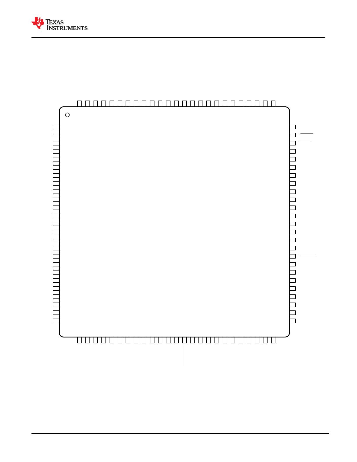
Device Information
(1)
PART NUMBER PACKAGE BODY SIZE (NOM)
TSB82AF15-EP 100 pin PZT
14.00 mm × 14.00
mm
(1) For all available packages, see the orderable addendum at
the end of the data sheet.
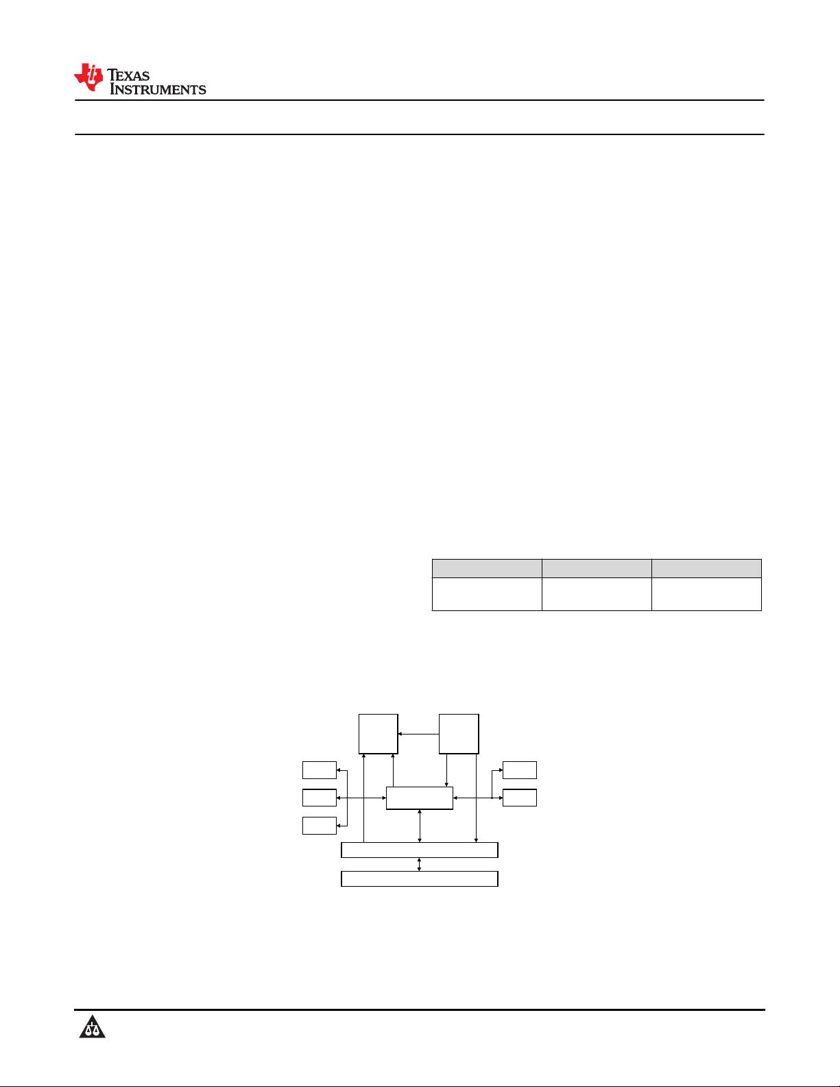
PCI Express
Transmitter
PCI Express
Receiver
PCI Bus Interface
Configuration and
Memory Register
GPIO
Serial
EEPROM
Reset
Controller
Clock
Generator
Power
Mgmt
1394b OHCI
Simplified Block Diagram
www.ti.com
TSB82AF15-EP
SCPS271 – JULY 2020
Copyright © 2020 Texas Instruments Incorporated
Submit Document Feedback
1
Product Folder Links: TSB82AF15-EP
TSB82AF15-EP
SCPS271 – JULY 2020
An IMPORTANT NOTICE at the end of this data sheet addresses availability, warranty, changes, use in safety-critical applications,
intellectual property matters and other important disclaimers. PRODUCTION DATA.
Table of Contents
1 Features............................................................................1
2 Applications..................................................................... 1
3 Description.......................................................................1
4 Revision History.............................................................. 2
5 Pin Configuration and Functions...................................3
6 Specifications.................................................................. 8
6.1 Absolute Maximum Ratings ....................................... 8
6.2 ESD Ratings .............................................................. 8
6.3 Recommended Operating Conditions ........................8
6.4 Thermal Information ...................................................8
6.5 PCIe Differential Transmitter Output Ranges .............8
6.6 PCIe Differential Receiver Input Ranges ..................11
6.7 PCIe Differential Reference Clock Input Ranges .....13
6.8 Electrical Characteristics Over Recommended
Operating Conditions (3.3-V I/O) ................................13
6.9 Switching Characteristics .........................................13
7 Operating Life Deration.................................................14
8 Typical Characteristics................................................. 15
9 Parameter Measurement Information.......................... 16
10 Detailed Description....................................................17
10.1 Overview................................................................. 17
10.2 Functional Block Diagram....................................... 17
10.3 Feature Description.................................................18
10.4 Device Functional Modes........................................30
10.5 Programming.......................................................... 32
10.6 Register Maps.........................................................33
11 Application and Implementation.............................. 164
11.1 Known exceptions to functional specification
(errata).......................................................................164
11.2 Application Information..........................................165
12 Power Supply Recommendations............................167
13 Layout.........................................................................168
13.1 Layout Guidelines................................................. 168
14 Device and Documentation Support........................169
14.1 Device Support..................................................... 169
14.2 Documentation Support........................................ 169
14.3 Receiving Notification of Documentation Updates169
14.4 Support Resources............................................... 169
14.5 Trademarks...........................................................169
14.6 Electrostatic Discharge Caution............................170
14.7 Glossary................................................................170
15 Mechanical, Packaging, and Orderable
Information.................................................................. 171
15.1 Mechanical Data................................................... 172
4 Revision History
NOTE: Page numbers for previous revisions may differ from page numbers in the current version.
DATE REVISION NOTES
September 2020 * Initial release.
TSB82AF15-EP
SCPS271 – JULY 2020
www.ti.com
2 Submit Document Feedback
Copyright © 2020 Texas Instruments Incorporated
Product Folder Links: TSB82AF15-EP
5 Pin Configuration and Functions
The TSB82AF15-EP is packaged in a 100-pin PZT package.
100 VDDA_3326D7
1REFCLK+ 75 VSS
99 VSSA_PCIE27VDD_33
2REFCLK- 74 PERST
98 RXN28GPIO0
3VSSA 73 GRST
97 RXP29GPIO1
4VDD_33 72 VDD_33
96 VSSA_PCIE30GPIO2
5LPS 71 RSVD_VSS
95 VDDA_1531VSS
6PINT 70 RSVD_VSS
94 VSSA32GPIO3
7LINKON 69 RSVD
93 VDDA_1533GPIO4
8LREQ 68 VSS
92 VSS_PCIE34GPIO5
9VSS 67 RSVD
91 VDD_1535GPIO6
10PCLK 66 RSVD
90 VSSA_PCIE36VDD_15
11VDD_15 65 RSVD_VSS
89 TXN37GPIO7
12LCLK 64 VDD_15
88 TXP38VDD_15
13VDD_33 63 REFCLK_SEL
87 VSSA_PCIE39OHCI_PME
14CTL0 62 SDA
86 VDDA_1540VSS
15CTL1 61 SCL
85 VDDA_1541CYCLEOUT
16VSS 60 VSS
84 VDD_33_COMB42RSVD_VSS
17D0 59 CLKREQ
83 VDDA_3343RSVD
18D1 58 RSVD
82 VDD_33_AUX44VDD_33
19D2 57 VDD_33
81 VSS45RSVD
20VDD_15 56 RSVD
80 REF1_PCIE46RSVD
21D3 55 RSVD
79 REF0_PCIE47RSVD
22D4 54 RSVD
78 VSSA48VSS
23D5 53 VDD_15
77 VDD_33_COMBIO49RSVD
24VSS 52 RSVD
76 VDD_15_COMB50RSVD
25D6 51 RSVD
Not to scale
Figure 5-1. PZT Package 100-Pin QFP Top View
www.ti.com
TSB82AF15-EP
SCPS271 – JULY 2020
Copyright © 2020 Texas Instruments Incorporated
Submit Document Feedback
3
Product Folder Links: TSB82AF15-EP
Pin Functions
PIN
TYPE
(1)
DESCRIPTION
NAME NO.
REFCLK+ 1 DI
Reference clock positive. REFCLK+ and REFCLK- comprise the differential input pair for the
100-MHz system reference clock.
REFCLK- 2 DI
Reference clock negative. REFCLK+ and REFCLK- comprise the differential input pair for the
100-MHz system reference clock.
VSSA 3 P Analog ground.
VDD_33 4 P 3.3-V digital I/O power. Filter from VDDA_33 supply.
LPS 5 O
Link power status. This terminal must be connected to the LPS input terminal of the
connected PHY.
PINT 6 I
PHY interrupt. The connected PHY uses this signal to transfer status and interrupt information
serially to the LLC. This terminal must be connected to the PINT output of the connected PHY.
LINKON 7 I/O
Link-on notification. LINKON is an input to the LLC from the connected PHY that is used to
provide notification that a link-on packet has been received or an event, such as a port
connection, has occurred. This I/O only has meaning when LPS is disabled. This includes the
D0 (uninitialized), D2, and D3 power states. If LINKON becomes active in the D0
(uninitialized), D2, or D3 power state, the TSB82AF15-EP device sets bit 15 (PME_STS) in
the power-management control and status register in the PCI configuration space at offset
48h. This terminal must be connected to the LKON output terminal of the connected PHY.
LREQ 8 O
LLC request. The LLC uses this output to initiate a service request to the connected PHY. This
terminal must be connected to the LREQ input of the connected PHY.
VSS 9 P Digital ground.
PCLK 10 I PHY clock. This terminal must be connected to the PCLK output of the connected PHY.
VDD_15 11 P 1.5-V digital core power for the link. Filter from VDDA_15 supply.
LCLK 12 O LLC clock. This terminal must be connected to the LCLK input terminal of the connected PHY.
VDD_33 13 P 3.3-V digital I/O power. Filter from VDDA_33 supply.
CTL0 14 I/O
Control. CTL[1:0] are bidirectional control bus signals that are used to indicate the phase of
operation of the PHY link interface. Upon a reset of the interface, this bus is driven by the
PHY. When driven by the PHY, information on CTL[1:0] is synchronous to PCLK. When driven
by the link, information on CTL[1:0] is synchronous to LCLK. If not implemented, these
terminals should be left unconnected.
CTL1 15 I/O
Control. CTL[1:0] are bidirectional control bus signals that are used to indicate the phase of
operation of the PHY link interface. Upon a reset of the interface, this bus is driven by the
PHY. When driven by the PHY, information on CTL[1:0] is synchronous to PCLK. When driven
by the link, information on CTL[1:0] is synchronous to LCLK. If not implemented, these
terminals should be left unconnected.
VSS 16 P Digital ground.
D0 17 I/O
Data. D[7:0] comprise a bidirectional data bus that is used to carry 1394 packet data, packet
speed, and grant type information between the PHY and the link. Upon a reset of the
interface, this bus is driven by the PHY. When driven by the PHY, information on D[7:0] is
synchronous to PCLK. When driven by the link, information on D[7:0] is synchronous to LCLK.
If not implemented, these terminals should be left unconnected.
D1 18 I/O D1
D2 19 I/O D2
VDD_15 20 P 1.5-V digital core power for the link. Filter from VDDA_15 supply.
D3 21 I/O D3
D4 22 I/O D4
D5 23 I/O D5
VSS 24 P Digital ground.
D6 25 I/O D6
D7 26 I/O D7
VDD_33 27 P 3.3-V digital I/O power. Filter from VDDA_33 supply.
TSB82AF15-EP
SCPS271 – JULY 2020
www.ti.com
4 Submit Document Feedback
Copyright © 2020 Texas Instruments Incorporated
Product Folder Links: TSB82AF15-EP
PIN
TYPE
(1)
DESCRIPTION
NAME NO.
GPIO0 28 I/O
General-purpose I/O 0. This terminal functions as a GPIO controlled by bit 0 (GPIO0_DIR) in
the GPIO control register (See Section 10.6.1.60). Note: This terminal has an internal active
pullup resistor.
GPIO1 29 I/O
General-purpose I/O 1. This terminal functions as a GPIO controlled by bit 1 (GPIO1_DIR) in
the GPIO control register (See Section 10.6.1.60). Note: This terminal has an internal active
pullup resistor.
GPIO2 30 I/O
General-purpose I/O 2. This terminal functions as a GPIO controlled by bit 2 (GPIO2_DIR) in
the GPIO control register (See Section 10.6.1.60). Note: This terminal has an internal active
pullup resistor.
VSS 31 P Digital ground.
GPIO3 32 I/O
General-purpose I/O 3. This terminal functions as a GPIO controlled by bit 3 (GPIO3_DIR) in
the GPIO control register (See Section 10.6.1.60). Note: This terminal has an internal active
pullup resistor.
GPIO4 33 I/O
General-purpose I/O 4. This terminal functions as a GPIO controlled by bit 4 (GPIO4_DIR) in
the GPIO control register (See Section 10.6.1.60). Note: This terminal has an internal active
pullup resistor.
GPIO5 34 I/O
General-purpose I/O 5. This terminal functions as a GPIO controlled by bit 5 (GPIO5_DIR) in
the GPIO control register (See Section 10.6.1.60). Note: This terminal has an internal active
pullup resistor.
GPIO6 35 I/O
General-purpose I/O 6. This terminal functions as a GPIO controlled by bit 6 (GPIO6_DIR) in
the GPIO control register (See Section 10.6.1.60). Note: This terminal has an internal active
pullup resistor.
VDD_15 36 P 1.5-V digital core power for the link. Filter from VDDA_15 supply.
GPIO7 37 I/O
General-purpose I/O 7. This terminal functions as a GPIO controlled by bit 7 (GPIO7_DIR) in
the GPIO control register (See Section 10.6.1.60). Note: This terminal has an internal active
pullup resistor.
VDD_15 38 P 1.5-V digital core power for the link. Filter from VDDA_15 supply.
OHCI_PME# 39 O
OHCI power-management event. This is an optional signal that can be used by a device to
request a change in the device or system power state. This signal must be enabled by
software.
VSS 40 P Digital ground.
CYCLEOUT 41 O
Cycle out. This terminal provides an 8-kHz cycle timer synchronization signal. If not
implemented, this terminal should be left unconnected.
RSVD_VSS 42 I Reserved pin, connect to VSS.
RSVD 43 O Reserved pin, leave unconnected.
VDD_33 44 P 3.3-V digital I/O power. Filter from VDDA_33 supply.
RSVD 45 O Reserved pin, leave unconnected.
RSVD 46 O Reserved pin, leave unconnected.
RSVD 47 O Reserved pin, leave unconnected.
VSS 48 P Digital ground.
RSVD 49 O Reserved pin, leave unconnected.
RSVD 50 O Reserved pin, leave unconnected.
RSVD 51 O Reserved pin, leave unconnected.
RSVD 52 O Reserved pin, leave unconnected.
VDD_15 53 P 1.5-V digital core power for the link. Filter from VDDA_15 supply.
RSVD 54 O Reserved pin, leave unconnected.
RSVD 55 O Reserved pin, leave unconnected.
RSVD 56 O Reserved pin, leave unconnected.
VDD_33 57 P 3.3-V digital I/O power. Filter from VDDA_33 supply.
RSVD 58 O Reserved pin, leave unconnected.
www.ti.com
TSB82AF15-EP
SCPS271 – JULY 2020
Copyright © 2020 Texas Instruments Incorporated
Submit Document Feedback
5
Product Folder Links: TSB82AF15-EP
剩余176页未读,继续阅读
资源评论
不觉明了
- 粉丝: 3164
- 资源: 5429
上传资源 快速赚钱
- 我的内容管理 展开
- 我的资源 快来上传第一个资源
- 我的收益 登录查看自己的收益
- 我的积分 登录查看自己的积分
- 我的C币 登录后查看C币余额
- 我的收藏
- 我的下载
- 下载帮助
安全验证
文档复制为VIP权益,开通VIP直接复制
信息提交成功