


High
D
e
f
i
n
i
t
i
o
n
LiDAR
™
S
e
n
s
o
r
H
D
L
-
64
E
S
2
and
S
2
.
1
U
S
E R
’
S
M A N U A L A N
D
P R O G R A M M
I
N G G U
I
D E
F
i
r
m
w
a
r
e Ve
r
s
i
o
n 4
.
0
7

i
1
S
A
F E T Y N O T I
C E S
I N T R O D U C T I O N
In The Box
P R I N C I P L E S O F O P E R A T I O N
16
A
P
P
E
N
D
I
X
B
:
Wiring Diagram
17
17
17
17
18
18
19
19
A
P
P
E
N
D
I
X
C
:
Digital Sensor Recorder
(DSR)
Install
Calibrate
Live Playback
Record Data
Playback of Recorded Files
DSR Key Controls
DSR Mouse Controls
2
3
3
4
5
6
I N S T
A
L L
A
T I O N O V E R V I E W
FrontlBack Mounting
Side Mounting
Top Mounting
Wiring
U S
A
G E
Use the Included Point-cloud Viewer
Develop Your Own Application-specific
Point-cloud Viewer
db.xml Calibration Parameters
Change Run-Time Parameters
Control Spin Rate
— Change Spin Rate in Flash Memory
— Change Spin Rate in RAM Only
Limit Horizontal FOV data Collected
Define Sensor Memory IP Source
and Destination Addresses
Upload Calibration Data
External GPS Time Synchronization
— GPS Receiver Option 1:
Velodyne Supplied GPS Receiver
— GPS Receiver Option 2:
Customer Supplied GPS Receiver
Packet Format and Status Byte
for GPS Time Stamping
Time Stamping Accuracy Rules
Laser Firing Sequence and Timing
6
6
6
A
P
P
E
N
D
I
X
D
:
Matlab Sample Code
Reading Calibration and Sensor Parameter Data
2O
1O
11
A
P
P
E
N
D
I
X
G
:
Ethernet
T
ransmit
T
iming
T
able
34
A
P
P
E
N
D
I
X
H
:
Laser and Detector
A
rrangement
36
11
11
A
P
P
E
N
D
I
X
I
:
A
ngular Resolution
37
T
R
O
U
B
L
E
S
H
O
O T I N G
S E R V I C E A N D M A I N T E N A N C E
S P E C I F I C A T I O N S
38
38
39
13
13
13
14
F I R M W
A
R E U P D
A
T E
15
A
P P E N D I X
A
:
Mechanical Drawings
22
A
P
P
E
N
D
I
X
E
:
Data Packet Format
Last Six Bytes Examples
7
8
1O
23
27
3O
A
P
P
E
N
D
I
X
F
:
Dual
T
wo Point Calibration
Methodology

C
A
U
T
I
O
N —
S
A
F
E
TY NOTI
C
E
Caution
To reduce the risk of electric shock and to avoid violating the warranty, do not open sensor body. Refer servicing
to qualified service personnel.
The lightning flash with arrowhead symbol is intended to alert the user to the presence of uninsulated
“dangerous voltage” within the product’s enclosure that may be of sufficient magnitude to constitute a risk o
f
electric shock to persons.
The exclamation point symbol is intended to alert the user to the presence of important operating and
maintenance (servicing) instructions in the literature accompanying the product.
1.
2.
3.
4.
5.
Read Instructions
—
A
ll safety and operating instructions should be read
before the produ
c
t
is operated.
Retain Instructions — The safety and operating instructions should be retained for future reference.
Heed Warnings — All warnings on the product and in the operating instructions should be adhered to.
Follow Instructions — All operating and use instructions should be followed.
Servicing — The user should not attempt to service the product beyond what is described in the operating
instructions. All other servicing should be referred to Velodyne.
1
[
i
]

I
N
T
R
O
D
U
C
T
I
O
N
H
D
L
-
64
E
S2
and
S2.1
U
s
e
r
’
s
Ma nua
l
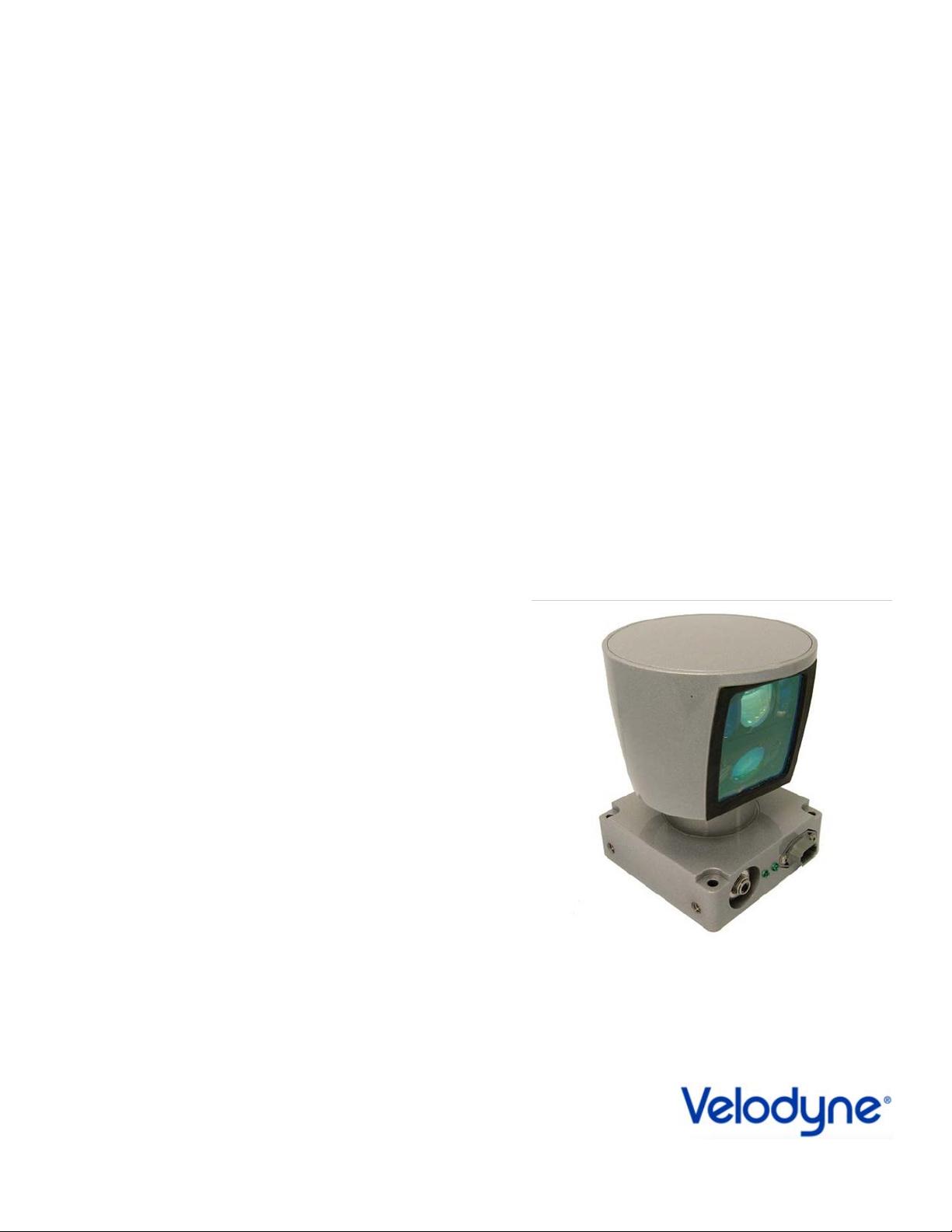
Congratulations on your purchase of a
V
elodyne HDL-64E
S2
or
S2.1
High
Definition
LiD
A
R
Sensor.
These
sensors represent a
breakthrough in sensing technology by providing more information about the surrounding environment than previously
possible. The HDL-64E S2 or S2.1 High Definition LiDAR sensors are referred to as the sensor throughout this manual.
This manual and programming guide covers:
• Installation and wiring
• HDL-64-ADAPT (GPS Adaptor Box)
• The data packet format
• The serial interface
• Software updates
• GPS installation notes
• Viewing the data
• Programming information
This manual applies to the two versions of the HDL-64E
sensor,
the
S2
and
S2.1,
unless
otherwise
indicated. The table below compares
the
laser layout, vertical field of view (VFOV) and primary application of the two versions.
1/3° vertical spacing %° vertical spacing
32 lasers separated by
3D mapping
F
or the latest updates to this manual
—
check www.velodynelidar.com.
In
the
B
o
x
Each shipment contains:
• Sensor
• HDL-64-ADAPT (GPS Adaptor Box)
• Wiring harness
• CD with user manual, calibration file (db.xml), timing table calculation file (.xls) and DSR viewer
S2.1
(dual lower block)
32 lasers separated by
%° vertical spacing
32 lasers separated by
%° vertical spacing
31.5°
Vertical Field of View (VFOV)
Primary Application
+2 to -24.8°
Autonomous navigation
Upper Laser Block
32 lasers separated by
Lower Laser Block
HDL-64E Version
S2
[ 1
]

P
R
I
N
C
I
P
L
E
S
O
F O
P
E
R
A
T
I
O
N
H
D
L
-
64
E
S2
and
S2.1
U
s
e
r
’
s
Ma nua
l
The sensor operates, instead of a
single laser firing through
a
rotating
mirror,
with
64
lasers
fixed
mounted
on upper and lower laser
blocks,
each housing 32 lasers. Both laser blocks rotate as a single unit. With this design each of the lasers fires tens of thousands of times per
second, providing exponentially more data points/second and a more data-intensive point cloud than a rotating mirror design. The sensor
delivers a 360° horizontal Field of View (HFOV) and a 26.8° vertical FOV (31.5° VFOV for the S2.1).
A
dditionall
y
, state-of-the-art digital
signal processing and
waveform
analysis
are
employed
to
provide
high
accurac
y
, extended distance
sensing and intensity data. The sensor is rated to provide usable returns up to 120 meters. The sensor employs a direct drive motor
system with no belts or chains in the drive train.
See the specifications at the end of this manual for more
information
about
sensor
operating
conditions.
L
a
s
e
r
R
e
c
e
i
v
e
r
s
(Groups of 32)
H
o
u
s
i
n
g
(Entire unit spins
at 5-20 Hz)
Motor
H
o
u
s
i
n
g
L
a
s
e
r
E
m
i
tt
e
r
s
(Groups of 16)
Figure
1.
HDL
-
64
E
S
2
design overview.
[ 2
]


评论3