IEEE TRANSACTIONS ON POWER SYSTEMS, VOL. 25, NO. 1, FEBRUARY 2010 531
Security-Constrained Unit Commitment
With AC/DC Transmission Systems
Azim Lotfjou, Member, IEEE, Mohammad Shahidehpour, Fellow, IEEE, Yong Fu, Member, IEEE, and
Zuyi Li, Member, IEEE
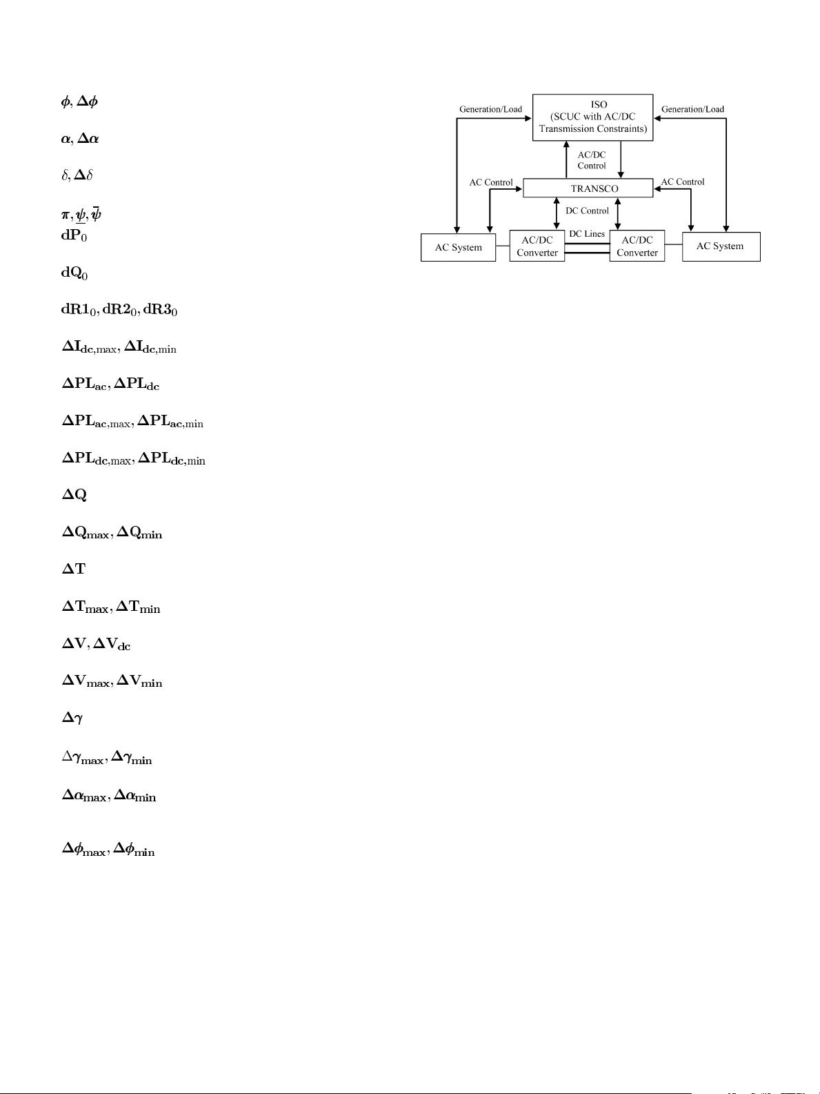
Abstract—This paper presents the solution to the security- con-
strained unit commitment (SCUC) problem with a detailed repre-
sentation of high voltage direct current (DC) transmission system
with current source converters (CSCs). The SCUC problem is de-
composed into a master problem for solving unit commitment (UC)
problem and hourly transmission security check subproblems that
evaluate branch flows and bus voltages of integrated AC/DC trans-
mission systems. The solution of the transmission security check
subproblem is based on a linear programming (LP) formulation
that minimizes AC bus mismatches subject to AC/DC transmission
constraints. The final SCUC solution prescribes an economic and
secure operation and control strategy for AC/DC transmission sys-
tems and coordinates DC power transfers for enhancing the eco-
nomics and the security of AC transmission systems. Numerical
tests illustrate the efficiency of the proposed AC/DC transmission
model.
Index Terms—AC/DC transmission systems, Benders decom-
position, current source converters, security-constrained unit
commitment.
NOMENCLATURE
Index for AC buses.
Index for contingencies.
Index for DC converters.
Index for generating units.
Index for transmission lines.
Index for AC bus terminals
connected to converters.
DC current of converter .
Slack variables for the real power
mismatch at bus
.
Slack variables for the reactive
power mismatch at bus
.
NB Number of AC buses.
Real and reactive power
withdrawals at bus
.
Real and reactive power
injections at bus
.
Manuscript received June 05, 2009; revised July 10, 2009. First published
December 31, 2009; current version published January 20, 2010. Paper no.
TPWRS-00084-2009.
The authors are with the Department of Electrical and Computer Engineering,
Illinois Institute of Technology, Chicago, IL 60616 USA.
Color versions of one or more of the figures in this paper are available online
at http://ieeexplore.ieee.org.
Digital Object Identifier 10.1109/TPWRS.2009.2036486
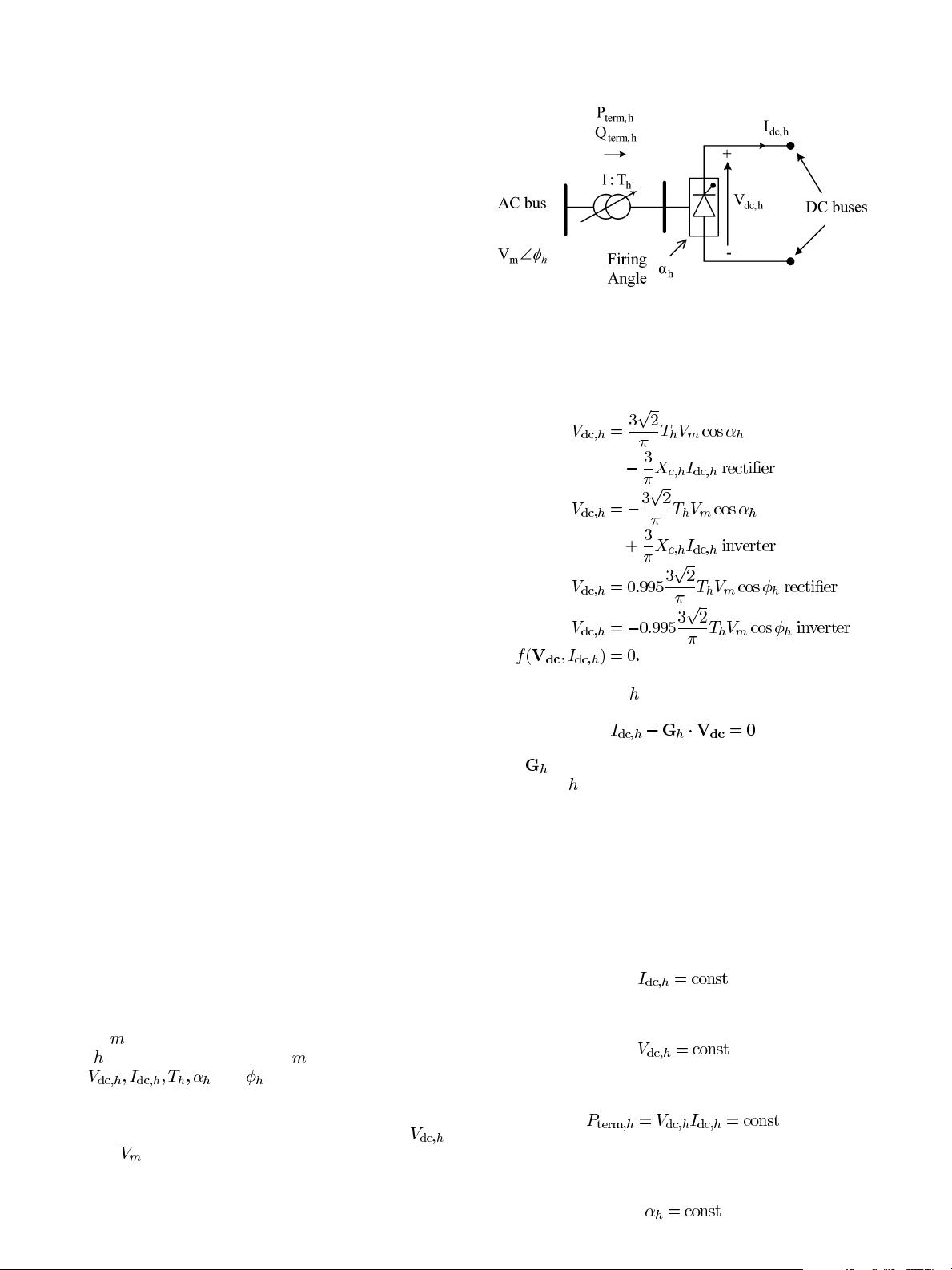
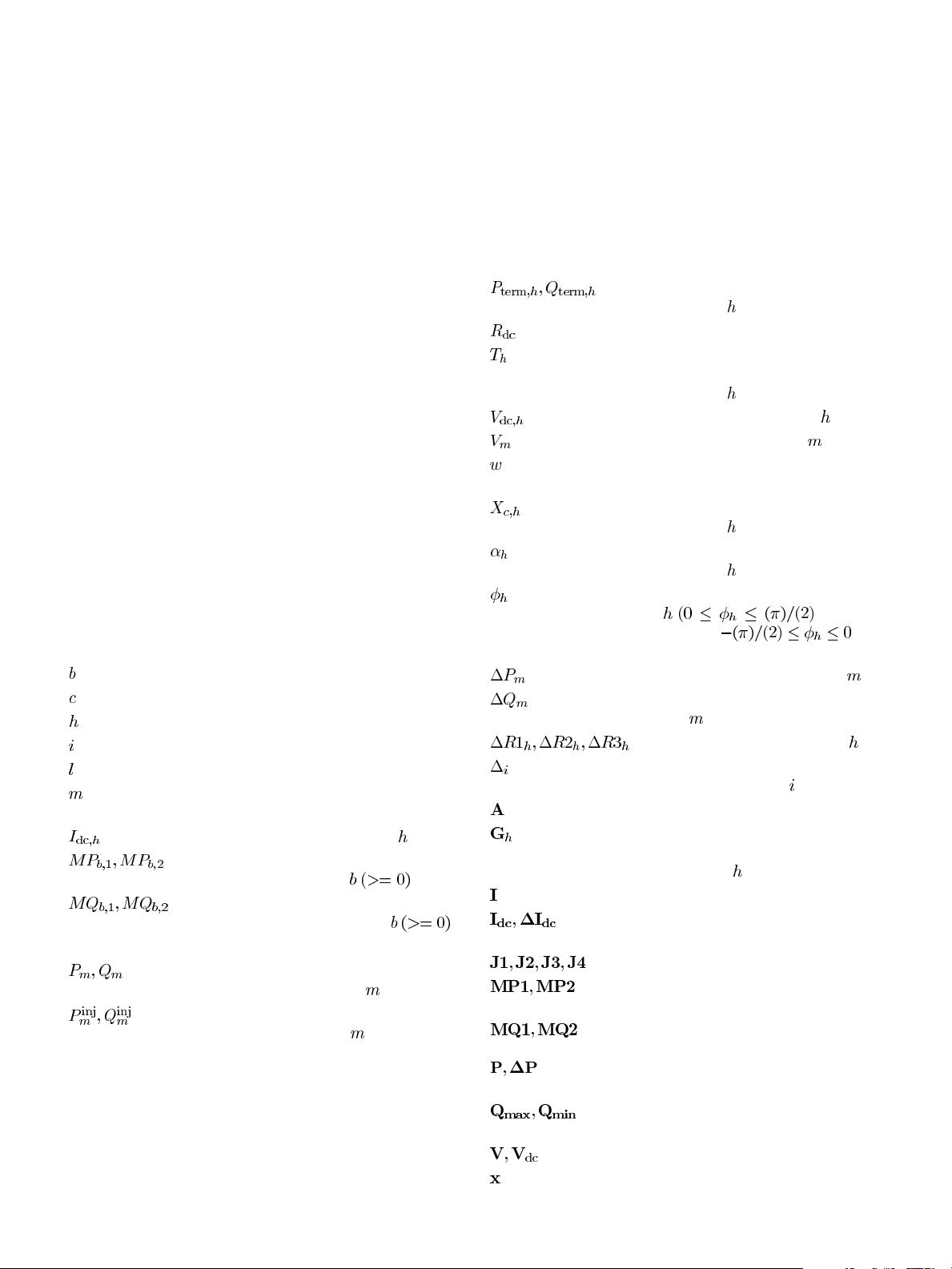
Real and reactive power of
converter
.
Resistance of DC line.
Off-nominal tap ratio of the
transformer connected to
converter
.
DC voltage of converter .
AC bus voltage at bus .
Objective value of SCUC
subproblem.
Commutation reactance of
converter
.
Firing/extinction angle of
converter
.
Power factor angle of converter
for
rectifier,
for
inverter).
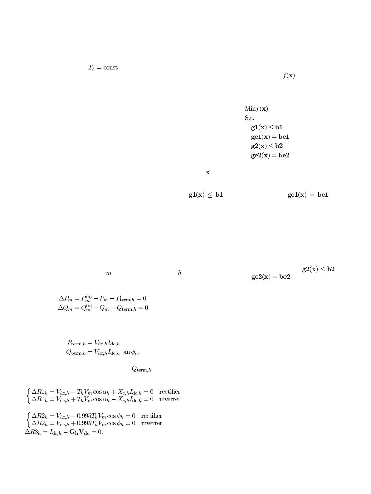
Real power mismatch at bus .
Reactive power mismatch at
bus
.
DC mismatches of converter .
Permissible real power
adjustment for unit
.
Bus-unit incidence matrix.
Admittance matrix of DC
transmission system for
converters
.
Unit state vector.
DC current vector and its
incremental vector.
Jacobian matrices.
Mismatch vector for real power
slack variables.
Mismatch vector for reactive
power slack variables.
Real power generation vector and
its increment.
Upper and lower limit vectors for
reactive power generation.
AC and DC bus voltage vectors.
Vector of SCUC variables.
0885-8950/$26.00 © 2009 IEEE