


CPRI Specification V4.2 (2010-09-29)
Interface Specification
Common Public Radio Interface (CPRI);
Interface Specification
The CPRI specification has been developed by Ericsson AB, Huawei Technologies Co. Ltd, NEC Corporation, Alcatel Lucent and Nokia Siemens
Networks GmbH & Co. KG (the “Parties”) and may be updated from time to time. Further information about CPRI, and the latest specification,
may be found at http://www.cpri.info
BY USING THE CPRI SPECIFICATION, YOU ACCEPT THE “Interface Specification Download Terms and Conditions” FOUND AT
http://www.cpri.info/spec.html
IN ORDER TO AVOID ANY DOUBT, BY DOWNLOADING AND/OR USING THE CPRI SPECIFICATION NO EXPRESS OR IMPLIED LICENSE
A
ND/OR ANY OTHER RIGHTS WHATSOEVER ARE GRANTED FROM ANYBODY.
© 2009 Ericsson AB, Huawei Technologies Co. Ltd, NEC Corporation, Alcatel Lucent, and Nokia Siemens Networks GmbH & Co. KG.
.

CPRI
CPRI Specification V4.2 (2010-09-29)2
Table of Contents
1. Introduction ...................................................................................................................4
2. System Description.......................................................................................................6
2.1. Definitions/Nomenclature...............................................................................6
2.2. System Architecture........................................................................................9
2.3. Reference Configurations.............................................................................10
2.4. Functional Description..................................................................................13
2.4.1. Radio Functionality ............................................................................13
2.4.2. CPRI Control Functionality ................................................................14
3. Interface Baseline........................................................................................................15
3.1. Supported Radio Standards.........................................................................15
3.2. Operating Range............................................................................................15
3.3. Topology/Switching/Multiplexing ................................................................15
3.4. Bandwidth/Capacity/Scalability ...................................................................17
3.4.1. Capacity in terms of Antenna-Carriers...............................................17
3.4.2. Required U-plane IQ Sample Widths.................................................18
3.4.3. Required C&M-plane Bit Rate ...........................................................19
3.5. Synchronization/Timing................................................................................19
3.5.1. Frequency Synchronization ...............................................................19
3.5.2. Frame Timing Information .................................................................20
3.5.3. Link Timing Accuracy ........................................................................21
3.5.4. Round Trip Delay Accuracy...............................................................21
3.5.5. Accuracy of TDD Tx-Rx switching point ............................................22
3.6. Delay Calibration ...........................................................................................22
3.6.1. Round Trip Cable Delay per Link ......................................................22
3.6.2. Round Trip Delay of a Multi-hop Connection.....................................23
3.7. Link Maintenance ..........................................................................................23
3.8. Quality of Service ..........................................................................................24
3.8.1. Maximum Delay.................................................................................24
3.8.2. Bit Error Ratio U-plane ......................................................................24
3.8.3. Bit Error Ratio C&M-plane .................................................................24
3.9. Start-up Requirement....................................................................................25
3.9.1. Clock Start-up Time Requirement .....................................................25
3.9.2. Plug and Play Requirement...............................................................25
4. Interface Specification................................................................................................27
4.1. Protocol Overview.........................................................................................27
4.2. Physical Layer (Layer 1) Specification........................................................28
4.2.1. Line Bit Rate ......................................................................................28
4.2.2. Physical Layer Modes .......................................................................28
4.2.3. Electrical Interface .............................................................................30
4.2.4. Optical Interface ................................................................................30
4.2.5. Line Coding .......................................................................................30
4.2.6. Bit Error Correction/Detection............................................................30
4.2.7. Frame Structure.................................................................................30
4.2.8. Synchronisation and Timing ..............................................................55
4.2.9. Link Delay Accuracy and Cable Delay Calibration ............................56
4.2.10. Link Maintenance of Physical Layer ..................................................59
4.3. Data Link Layer (Layer 2) Specification for Slow C&M Channel...............64
4.3.1. Layer 2 Framing ................................................................................64
4.3.2. Media Access Control/Data Mapping ................................................64
4.3.3. Flow Control ......................................................................................65
4.3.4. Control Data Protection/ Retransmission Mechanism .......................65
4.4. Data Link Layer (Layer 2) Specification for Fast C&M Channel................65

CPRI
CPRI Specification V4.2 (2010-09-29)3
4.4.1. Layer 2 Framing ................................................................................65
4.4.2. Media Access Control/Data Mapping ................................................66
4.4.3. Flow Control ......................................................................................68
4.4.4. Control Data Protection/ Retransmission Mechanism .......................68
4.5. Start-up Sequence.........................................................................................68
4.5.1. General..............................................................................................68
4.5.2. Layer 1 Start-up Timer.......................................................................69
4.5.3. State Description ...............................................................................70
4.5.4. Transition Description........................................................................74
5. Interoperability ............................................................................................................77
5.1. Forward and Backward Compatibility .........................................................77
5.1.1. Fixing Minimum Control Information Position in CPRI Frame
Structure ............................................................................................77
5.1.2. Reserved Bandwidth within CPRI......................................................77
5.1.3. Version Number.................................................................................77
5.1.4. Specification Release Version mapping into CPRI Frame ................77
5.2. Compliance ....................................................................................................78
6. Annex ...........................................................................................................................79
6.1. Delay Calibration Example (Informative).....................................................79
6.2. Electrical Physical Layer Specification (Informative) ................................82
6.2.1. Overlapping Rate and Technologies .................................................82
6.2.2. Signal Definition.................................................................................83
6.2.3. Eye Diagram and Jitter ......................................................................83
6.2.4. Reference Test Points .......................................................................84
6.2.5. Cable and Connector.........................................................................84
6.2.6. Impedance.........................................................................................84
6.2.7. AC Coupling ......................................................................................84
6.2.8. TX Performances...............................................................................85
6.2.9. Receiver Performances .....................................................................90
6.2.10. Measurement Procedure ...................................................................93
6.3. Networking (Informative) ..............................................................................94
6.3.1. Concepts ...........................................................................................94
6.3.2. Reception and Transmission of SAP
CM
by the RE.............................94
6.3.3. Reception and Transmission of SAP
IQ
by the RE..............................95
6.3.4. Reception and Distribution of SAP
S
by the RE ..................................95
6.3.5. Reception and Transmission of CPRI Layer 1 Signalling by the
RE......................................................................................................95
6.3.6. Bit Rate Conversion...........................................................................95
6.3.7. More than one REC in a radio base station.......................................95
6.3.8. The REC as a Networking Element...................................................96
6.4. E-UTRA sampling rates (Informative)..........................................................96
6.5. Scrambling (Normative)................................................................................96
6.5.1. Transmitter.........................................................................................97
6.5.2. Receiver ..........................................................................................100
7. List of Abbreviations.................................................................................................101
8. References.................................................................................................................104
9. History........................................................................................................................105

CPRI
CPRI Specification V4.2 (2010-09-29)4
1. Introduction
The Common Public Radio Interface (CPRI) is an industry cooperation aimed at defining a publicly available
specification for the key internal interface of radio base stations between the Radio Equipment Control (REC)
and the Radio Equipment (RE). The parties cooperating to define the specification are Ericsson AB, Huawei
Technologies Co. Ltd, NEC Corporation, Alcatel Lucent and Nokia Siemens Networks GmbH & Co. KG.
Motivation for CPRI:
The CPRI specification enables flexible and efficient product differentiation for radio base stations and
independent technology evolution for Radio Equipment (RE) and Radio Equipment Control (REC).
Scope of Specification:
The necessary items for transport, connectivity and control are included in the specification. This includes
User Plane data, Control and Management Plane transport mechanisms, and means for synchronization.
A focus has been put on hardware dependent layers (layer 1 and layer 2). This ensures independent
technology evolution (on both sides of the interface), with a limited need for hardware adaptation. In addition,
product differentiation in terms of functionality, management, and characteristics is not limited.
With a clear focus on layer 1 and layer 2 the scope of the CPRI specification is restricted to the link interface
only, which is basically a point to point interface. Such a link shall have all the features necessary to enable a
simple and robust usage of any given REC/RE network topology, including a direct interconnection of multi-
port REs.
Redundancy mechanisms are not described in the CPRI specification, however all the necessary features to
support redundancy, especially in system architectures providing redundant physical interconnections (e.g.
rings) are defined.
CPRI
CPRI Specification V4.2 (2010-09-29)5
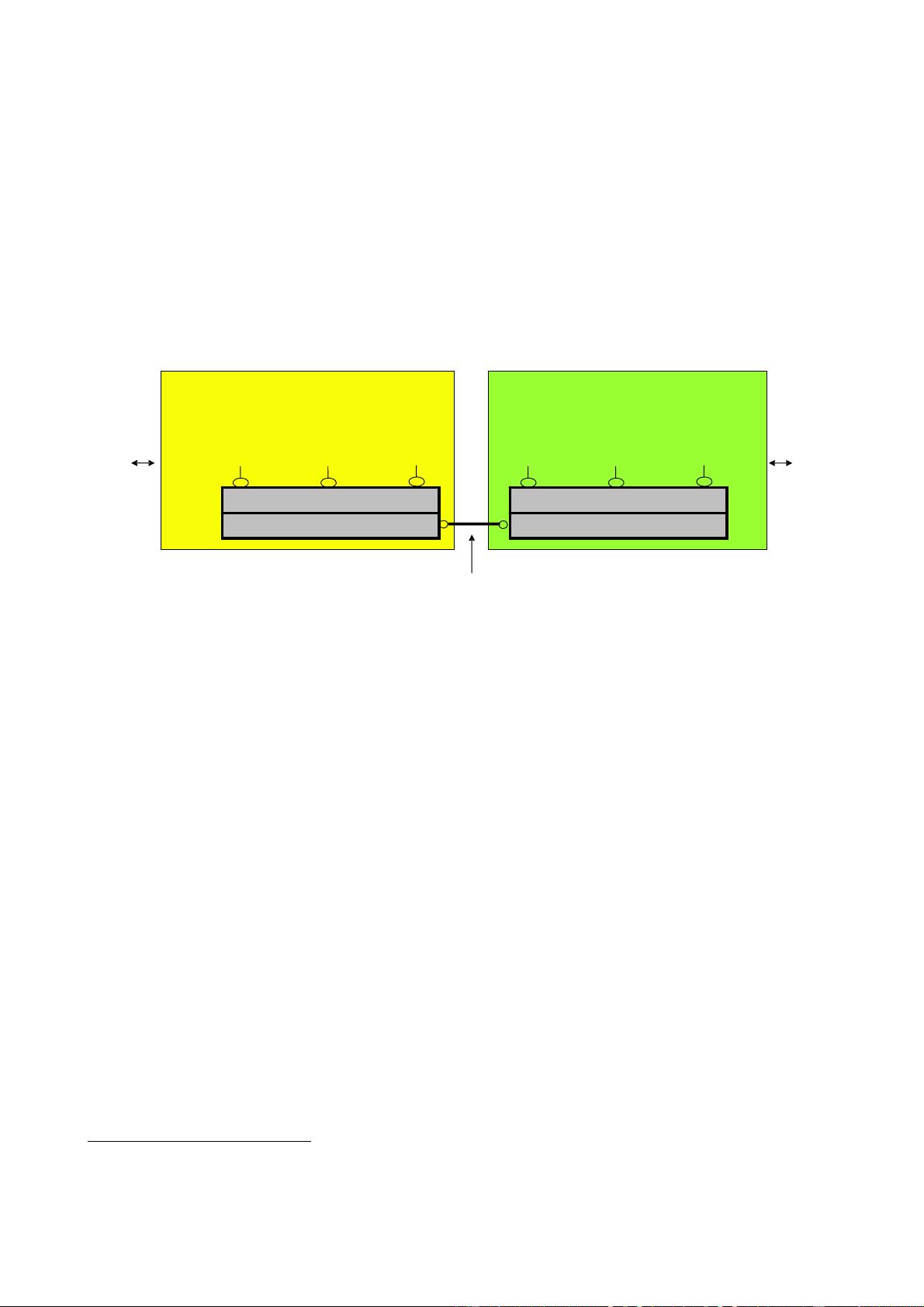
The specification has the following scope (with reference to Figure 1):
1. A digitized and serial internal radio base station interface that establishes a connection between
‘Radio Equipment Control’ (REC) and ‘Radio Equipment’ (RE) enabling single-hop and multi-hop
topologies is specified.
1
2. Three different information flows (User Plane data, Control and Management Plane data, and
Synchronization Plane data) are multiplexed over the interface.
3. The specification covers layers 1 and 2.
3a. The physical layer (layer 1) supports both an electrical interface (e.g., what is used in traditional
radio base stations), and an optical interface (e.g. for radio base stations with remote radio
equipment).
3b. Layer 2 supports flexibility and scalability.
Figure 1: System and Interface Definition
1
The CPRI specification may be used for any internal radio base station interface that carries the information flows mentioned in the
scope of point 2.
Radio Equipment (RE) Radio Equipment Control (REC)
Layer 1
Layer 2
Control &
Mgmt.
Use
r
Sync.
A
ir
Interface
Network
Interface
DigitizedRadio Base Station
Internal Interface Specification
Layer 1
Layer 2
Control &
Mgmt.
Use
r
Sync.


评论0