


Applications Systems Standardization Working Group
Interface Specifications
Interface 2
Version 1.0 of 31 March 1994

Interface ASAP2 Detailed Specification
Issue: Version 1.0 dated 31.3.94, translated 950622 Page 2 of 120
C. Larsson, Volvo Car Corporation, 96562
ASAP2: STANDARDIZED
DESCRIPTION DATA
Authors: Dr. H. Schelling Fa. Vector Informatik
Dipl.-Ing. P.Lampert Fa. Vector Informatik
Dr. C. Dallmayr Fa. Softing
Dipl.-Inf. G.Luderböck Fa. Softing
Version: 1.0
Date: 31 March 1994

Interface ASAP2 Detailed Specification
Issue: Version 1.0 dated 31.3.94, translated 950622 Page 3 of 120
C. Larsson, Volvo Car Corporation, 96562
Contents
1 ASAP: Goals, Method, Interfaces____________________________________________5
2 Division _______________________________________________________________10
3 System Description (SG Verbund) __________________________________________11
4 Description Application Devices ____________________________________________13
4.1 Control unit management data ________________________________________________ 13
4.2 General description data (control unit internal structures) _________________________ 13
4.3 Interface Parameters (general parameters) ______________________________________ 14
4.3.1 Interface module (memory emulator) ___________________________________________________ 14
4.3.2 CAN bus _________________________________________________________________________ 14
4.3.3 ABUS____________________________________________________________________________14
4.3.4 Bus parameters for serial protocols (ISO)________________________________________________ 14
4.3.5 Analog interface ___________________________________________________________________ 15
4.4 Adjustment objects (one description per adjustment object) ________________________ 15
4.4.1 Deposit structure [CHARACTERISTIC, page 32] ________________________________________ 16
4.4.2 Bit pattern conversion (axis points and function values) ____________________________________ 16
4.4.3 Function orientation (Reference)[FUNCTION_LIST, page 55] ______________________________ 16
4.5 Measurement channel (one description per measurement; e.g. AD value, CAN signal,
source data, RAM cell) __________________________________________________________ 16
4.5.1 Deposit structure (measurement channel)________________________________________________ 17
4.5.1.1 Description of the interface module deposit structure___________________________________17
4.5.1.2 Description of the CAN deposit structure ____________________________________________ 17
4.5.1.3 Description of the ABUS deposit structure ___________________________________________ 17
4.5.1.4 Description of the series protocol deposit structure (ISO) _______________________________ 17
4.5.1.5 Analog interface deposit structure __________________________________________________ 17
4.5.2 Bit pattern conversion _______________________________________________________________ 17
4.5.3 Function orientation (reference) _______________________________________________________ 17
4.6 Conversion method __________________________________________________________ 18
4.7 Conversion tables ___________________________________________________________ 18
4.8 Function description [FUNCTION, page 54] _____________________________________ 18
4.9 Record layout [RECORD_LAYOUT, page 78] ___________________________________ 18
5 FORMAT OF THE DESCRIPTION FILE ___________________________________19
5.1 Hierarchic division of the keywords ____________________________________________ 19
5.2 Predefined data types ________________________________________________________ 20
5.3 Alphabetical list of keywords __________________________________________________ 22
5.3.1 A2ML____________________________________________________________________________22
5.3.2 ADDR_EPK_______________________________________________________________________ 23
5.3.3 AXIS_DESCR ____________________________________________________________________24
5.3.4 AXIS_PTS ________________________________________________________________________ 26
5.3.5 AXIS_PTS_REF ___________________________________________________________________28
5.3.6 AXIS_PTS_X, AXIS_PTS_Y _________________________________________________________ 29
5.3.7 BIT_MASK _______________________________________________________________________ 30
5.3.8 BYTE_ORDER ____________________________________________________________________31
5.3.9 CHARACTERISTIC ________________________________________________________________ 32
5.3.10 COEFFS_________________________________________________________________________ 34
5.3.11 COMPU_METHOD _______________________________________________________________ 35
5.3.12 COMPU_TAB ____________________________________________________________________ 37
5.3.13 COMPU_TAB_REF _______________________________________________________________ 38
5.3.14 COMPU_VTAB___________________________________________________________________ 39
5.3.15 CPU_TYPE ______________________________________________________________________ 40
5.3.16 CUSTOMER _____________________________________________________________________ 41
5.3.17 CUSTOMER_NO _________________________________________________________________ 42
5.3.18 DATA_SIZE _____________________________________________________________________ 43
5.3.19 DEPOSIT________________________________________________________________________ 44

Interface ASAP2 Detailed Specification
Issue: Version 1.0 dated 31.3.94, translated 950622 Page 4 of 120
C. Larsson, Volvo Car Corporation, 96562
5.3.20 ECU ____________________________________________________________________________ 45
5.3.21 EPK ____________________________________________________________________________ 46
5.3.22 EXTENDED LIMITS ______________________________________________________________ 47
5.3.23 FIX_AXIS_PAR __________________________________________________________________ 48
5.3.24 FIX_NO_AXIS_PTS_X, FIX_NO_AXIS_PTS_Y ________________________________________ 49
5.3.25 FNC_VALUES ___________________________________________________________________ 50
5.3.26 FORMULA ______________________________________________________________________51
5.3.27 FORMULA_INV__________________________________________________________________53
5.3.28 FUNCTION ______________________________________________________________________ 54
5.3.29 FUNCTION_LIST_________________________________________________________________ 55
5.3.30 HEADER ________________________________________________________________________ 56
5.3.31 IDENTIFICATION ________________________________________________________________ 57
5.3.32 MAX_GRAD_____________________________________________________________________ 58
5.3.33 MAX_REFRESH__________________________________________________________________59
5.3.34 MEASUREMENT _________________________________________________________________60
5.3.35 MEMORY_LAYOUT ______________________________________________________________ 62
5.3.36 MODULE _______________________________________________________________________ 64
5.3.37 MOD_COMMON _________________________________________________________________ 66
5.3.38 MOD_PAR_______________________________________________________________________ 67
5.3.39 MONOTONY ____________________________________________________________________ 69
5.3.40 NO_AXIS_PTS_X, NO_AXIS_PTS_Y_________________________________________________ 70
5.3.41 NO_OF_INTERFACES_____________________________________________________________ 71
5.3.42 NUMBER _______________________________________________________________________ 72
5.3.43 OFFSET_X, OFFSET_Y ____________________________________________________________ 73
5.3.44 PHONE_NO______________________________________________________________________ 74
5.3.45 PROJECT________________________________________________________________________ 75
5.3.46 PROJECT_NO____________________________________________________________________ 76
5.3.47 READ_ONLY ____________________________________________________________________ 77
5.3.48 RECORD_LAYOUT_______________________________________________________________ 78
5.3.49 RESERVED______________________________________________________________________ 81
5.3.50 RIP_ADDR_X, RIP_ADDR_Y, RIP_ADDR_W _________________________________________ 82
5.3.51 SHIFT_OP_X, SHIFT_OP_Y ________________________________________________________ 84
5.3.52 SRC_ADDR_X, SRC_ADDR_Y _____________________________________________________ 85
5.3.53 SUPPLIER_______________________________________________________________________ 86
5.3.54 SYSTEM_CONSTANT_____________________________________________________________ 87
5.3.55 S_REC_LAYOUT _________________________________________________________________ 88
5.3.56 USER ___________________________________________________________________________ 89
5.3.57 VERSION _______________________________________________________________________ 90
5.3.58 VIRTUAL _______________________________________________________________________91
6 Include mechanism ______________________________________________________92
6.1.1 Description of complex projects _______________________________________________________ 92
6.1.2 Description of interface-specific parameters _____________________________________________ 92
7 Interface-specific description data __________________________________________93
7.1 Format of the ASAP2 metalanguage ____________________________________________ 94
7.1.1 Grammar in the extended Backus-Naur format ___________________________________________94
7.2 Example of ASAP2 metalanguage ______________________________________________ 97
7.3 Example of description file ___________________________________________________ 102
8 Appendix A: A2ML Grammar ____________________________________________109
9 Appendix B: Record layouts ______________________________________________111
10 Glossary _____________________________________________________________114
11 Keyword index ________________________________________________________118
Interface ASAP2 Detailed Specification
Issue: Version 1.0 dated 31.3.94, translated 950622 Page 5 of 120
C. Larsson, Volvo Car Corporation, 96562
1 ASAP: Goals, Method, Interfaces
The working group for the standardization of application systems (ASAP) was created in the autumn of 1991 at the
initiative of the development boards of the German automobile manufacturers.The motivation is cost reduction based
on co-operation in non-product relevant fields. The initiative is supported by the automobile manufacturers Audi, BMW,
Mercedes-Benz, Porsche and VW together with the contractors active in this segment Bosch, Hella, Siemens, Temic,
VDO and free suppliers and automation suppliers such as AVL, Erphi, FEV, Schenk, Softing and Vector.
The working group for the standardization of application systems (ASAP) aims at making the tools and methods
generated during the development phase of vehicle electronics compatible with each other and hence
interchangeable.
To this end the system parts required for the application as well as for verification and testing are adapted to the
current, technical requirements in parallel with the design and development phase of the actual control units and thus
brought to a high maturity level. In practice these efforts make it possible to incorporate individual components of the
overall system into the process chain and to integrate them with other application environments.
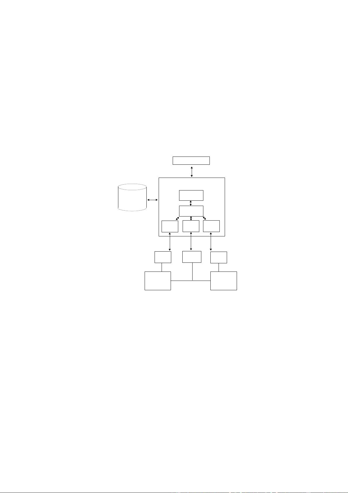
To reach these goals, the ASAP group has agreed to subdivide the overall system into sub-components (Figure 1)
using commonly defined interfaces that are compatible and interchangeable.
A
u
t
o
m
a
t
i
o
n
s
y
s
t
e
m
M
e
a
s
u
r
e
m
e
n
t
,
A
p
p
l
i
c
a
t
i
o
n
a
n
d
D
i
a
g
n
o
s
t
i
c
s
y
s
t
e
m
O
p
e
r
a
t
i
o
n
C
o
o
r
d
i
n
a
t
i
o
n
D
r
i
v
e
r
D
r
i
v
e
r
D
r
i
v
e
r
E
D
I
C
C
A
N
I
M
/
A
B
U
S
I
M
D
I
M
E
n
g
i
n
e
c
o
n
t
r
o
l
A
B
S
C
A
N
b
u
s
o
r
A
B
U
S
A
S
A
P
1
b
A
S
A
P
3
A
S
A
P
2
Figure 1 Overall system and interfaces
The individual application systems (AS) of the measurement, application and diagnostic system (MAD) are linked to
the automation via interface ASAP3, they obtain information about the control unit's internal elements, its interfaces
and communication methods from the ASAP2 description file, and are in turn linked to the control units (ECU) and the
control unit dependent measurement technology (ADC) via the ASAP1 interface via ROM emulators, CAN or ABUS or
the diagnostic bus (D bus). This structure allows current monolithic applications to be divided into compatible
subsystems.


评论0