


CAN Interface for USB
User Manual
PCAN-USB
Document version 2.6.0 (2019-03-05)

PCAN-USB – User Manual
2
Relevant products
Product name Model Part number
PCAN-USB IPEH-002021
PCAN-USB opto-decoupled Galvanic isolation for CAN
interface
IPEH-002022
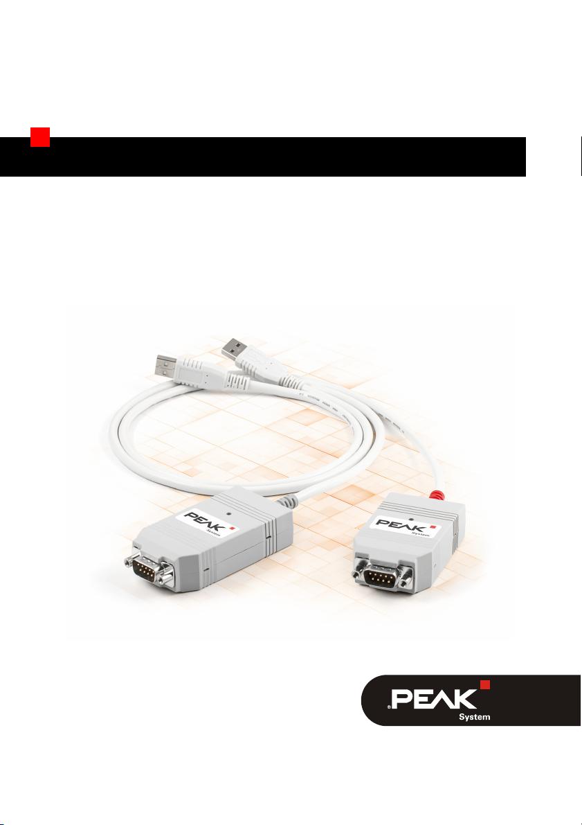
The cover picture shows both products: the PCAN-USB with the red and the PCAN-
USB opto-decoupled with the grey cable strain relief.
PCAN® is a registered trademark of PEAK-System Technik GmbH. CANopen® and
C
iA® are registered community trade marks of CAN in Automation e.V.
All other product names mentioned in this document may be the trademarks or
registered trademarks of their respective companies. They are not explicitly marked
by “™” or “®”.
Copyright © 2019 PEAK-System Technik GmbH
Duplication (copying, printing, or other forms) and the electronic distribution of this
document is only allowed with explicit permission of PEAK-System Technik GmbH.
PEAK-System Technik GmbH reserves the right to change technical data without
prior announcement. The general business conditions and the regulations of the
license agreement apply. All rights are reserved.
PEAK-System Technik GmbH
Otto-Roehm-Strasse 69
64293 Darmstadt
Germany
Phone: +49 (0)6151 8173-20
Fax: +49 (0)6151 8173-29
www.peak-system.com
info@peak-system.com
Doc
ument version 2.6.0 (2019-03-05)

PCAN-USB – User Manual
3
Contents
1 Introduction 5
1.1 Properties at a Glance 5
1.2 System Requirements 6
1.3 Scope of Supply 7
2 Installing the Software and the Adapter 8
3 Connecting the CAN Bus 9
3.1 Connection over D-Sub Connector 9
3.2 Voltage Supply of External Devices 10
3.3 Activating the Internal Termination 13
3.4 Cabling 15
3.4.1 Termination 15
3.4.2 Example of a Connection 15
3.4.3 Maximum Bus Length 16
4 Operation 17
4.1 Status LED 17
4.2 Unplugging the USB Connection 17
4.3 Distinguishing Several PCAN-USB Adapters 17
5 Software and API 18
5.1 Monitor Software PCAN-View 18
5.1.1 Receive/Transmit Tab 20
5.1.2 Trace Tab 22
5.1.3 PCAN-USB Tab 23
5.1.4 Status Bar 24
5.2 Linking Own Programs with PCAN-Basic 25
5.2.1 Features of PCAN-Basic 26
5.2.2 Principle Description of the API 27


PCAN-USB – User Manual
5
1 Introduction
The PCAN-USB adapter enables simple connection to CAN
networks. Its compact plastic casing makes it suitable for mobile
applications. The opto-decoupled version guarantees galvanic
isolation of up to 500 Volts between the PC and the CAN side.
The package is also supplied with the CAN monitor PCAN-View for
Windows and the programming interface PCAN-Basic.
Device drivers exist for different operating systems, so programs
can easily access a connected CAN bus.
Tip: At the end of this manual (Appendix C) you can find a
Quick Reference with brief information about the installation
and operation of the PCAN-USB adapter.
1.1 Properties at a Glance
Adapter for the USB connection (Full-Speed mode, compatible
with USB 1.1, USB 2.0, and USB 3.0)
High-Speed CAN connection (ISO 11898-2)
Bit rates from 5 kbit/s up to 1 Mbit/s
Time stamp resolution approx. 42 μs
Compliant with CAN specifications 2.0A (11-Bit ID)
and 2.0B (29-Bit ID)
CAN-Bus connection via D-Sub, 9-pin (in accordance with
CiA® 303-1)
NXP SJA1000 CAN controller, 16 MHz clock frequency
NXP PCA82C251 CAN transceiver


