PIC-WEB development board
Users Manual
Rev.A, July 2008
Copyright(c) 2008, OLIMEX Ltd, All rights reserved

INTRODUCTION:
PIC-WEB is compact board with 65x60 mm size which is supported by
Microchip’s open source TCP-IP stack AN833. The board is designed
with PIC18F452 microcontroller and ENC28J60 Ethernet controller and
supports: SLIP, ARP, IP, ICMP, TCP, UDP, HTTP, DHCP, FTP. The
Microchip stack is written on modular and flexible basis and you can
enable or disable modules. The stack also supports dynamic web pages
which give you the possibility to control all PIC resources remotely via
FTP, HTTP, UDP, TCP etc. With this board you can implement web and
ftp server, send e-mails and almost everything what a big server can do.
The on board 1Mbit serial flash is available for data storage
BOARD FEATURES:
− PIC18F452 microcontroller, ENC28J60 Ethernet controller
− 1Mbit on board serial flash for web pages storage
− ICSP/ICD connector for programming with PIC-MCP, PIC-MCP-USB and
programming and debugging with PIC-ICD2 and PIC-ICD2-POCKET.
− Reset button
− User event button
− Analogue trimmer potentiometer
− Thermistor for temperature monitoring
− RS232 driver and connector
− Complete web server and TCP-IP stack support as per Microchip's open
source TCP-IP stack
− Power plug-in jack for +5VDC power supply
− Voltage regulator +3.3V and filtering capacitors
− Status LED
− Extension header to connect to other boards
− Dimensions 60x65 mm (2.36x2.55")
ELECTROSTATIC WARNING:
The PIC-WEB board is shipped in protective anti-static packaging. The
board must not be subject to high electrostatic potentials. General practice
for working with static sensitive devices should be applied when working
with this board.
BOARD USE REQUIREMENTS:
Cables: Depends on the used programming/debugging tool. It could be
1.8 meter USB A-B cable to connect PIC-MCP-USB, PIC-ICD2
or PIC-ICD2-POCKET to USB host on PC or RS232 cable in
case of PIC-MCP or other programming/debugging tools. You
will need a serial cable if not for programming,
than for configuring the board. You will also need a LAN cable.
Hardware: Programmer/Debugger – most of Olimex programmers are
applicable, for example PIC-MCP, PIC-MCP-USB, PIC-ICD2,
PIC-ICD2-POCKET or other compatible
programming/debugging tool.

Software: PIC-WEB is tested with MPLAB IDE v.7.62 + MPLAB C18 C
compiler. It is possible that the stack might not function
properly if used with later versions of MPLAB IDE.
You will also need a terminal program configured at 19 200
bps, 8N1 and no flow control.
PROCESSOR FEATURES:
PIC-WEB board uses microcontroller PIC18F452 from Microchip with these
features:
- C compiler optimized architecture/instruction set
o Source code compatible with the PIC16C, PIC17C and PIC18C
instruction sets
- 32 Kbytes FLASH, 1536 bytes RAM and 256 bytes EEPROM on board
- Up to 10 MIPs operation:
o DC - 40 MHz osc./clock input
o 4 MHz - 10 MHz osc./clock input with PLL active
- 16-bit wide instructions, 8-bit wide data path
- Priority levels for interrupts
- 8 x 8 Single Cycle Hardware Multiplier
- High current sink/source 25 mA/25 mA
- Three external interrupt pins
- Timer0 module: 8-bit/16-bit timer/counter with 8-bit programmable
prescaler
- Timer1 module: 16-bit timer/counter
- Timer2 module: 8-bit timer/counter with 8-bit period register (time-base
for PWM)
- Timer3 module: 16-bit timer/counter
- Secondary oscillator clock option - Timer1/Timer3
- Two Capture/Compare/PWM (CCP) modules. CCP pins that can be
configured as:
o Capture input: capture is 16-bit, max. resolution 6.25 ns
(TCY/16)
o Compare is 16-bit, max. resolution 100 ns (TCY)
o PWM output: PWM resolution is 1- to 10-bit, Max. PWM freq. @:
8-bit resolution = 156 kHz and 10-bit resolution = 39 kHz
- Master Synchronous Serial Port (MSSP) module, Two modes of
operation:
o 3-wire SPI™ (supports all 4 SPI modes)
o I2C™ Master and Slave mode
- Addressable USART module:
o Supports RS-485 and RS-232
- Parallel Slave Port (PSP) module
- Compatible 10-bit Analog-to-Digital Converter module (A/D) with:
o Fast sampling rate
o Conversion available during SLEEP
o DNL = ±1 LSb, INL = ±1 LSb
- Programmable Low Voltage Detection (PLVD)
o Supports interrupt on-Low Voltage Detection
- Programmable Brown-out Reset (BOR)
- 100,000 erase/write cycle Enhanced FLASH program memory typical
- 1,000,000 erase/write cycle Data EEPROM memory
- FLASH/Data EEPROM Retention: > 40 years
- Self-reprogrammable under software control
- Power-on Reset (POR), Power-up Timer (PWRT) and Oscillator Start-up
Timer (OST)

- Watchdog Timer (WDT) with its own On-Chip RC Oscillator for reliable
operation
- Programmable code protection
- Power saving SLEEP mode
- Selectable oscillator options including:
o 4X Phase Lock Loop (of primary oscillator)
o Secondary Oscillator (32 kHz) clock input
- Single supply 5V In-Circuit Serial Programming™ (ICSP™) via two pins
- In-Circuit Debug (ICD) via two pins
- Low power, high speed FLASH/EEPROM technology
- Fully static design
- Wide operating voltage range (2.0V to 5.5V)
- Industrial and Extended temperature ranges
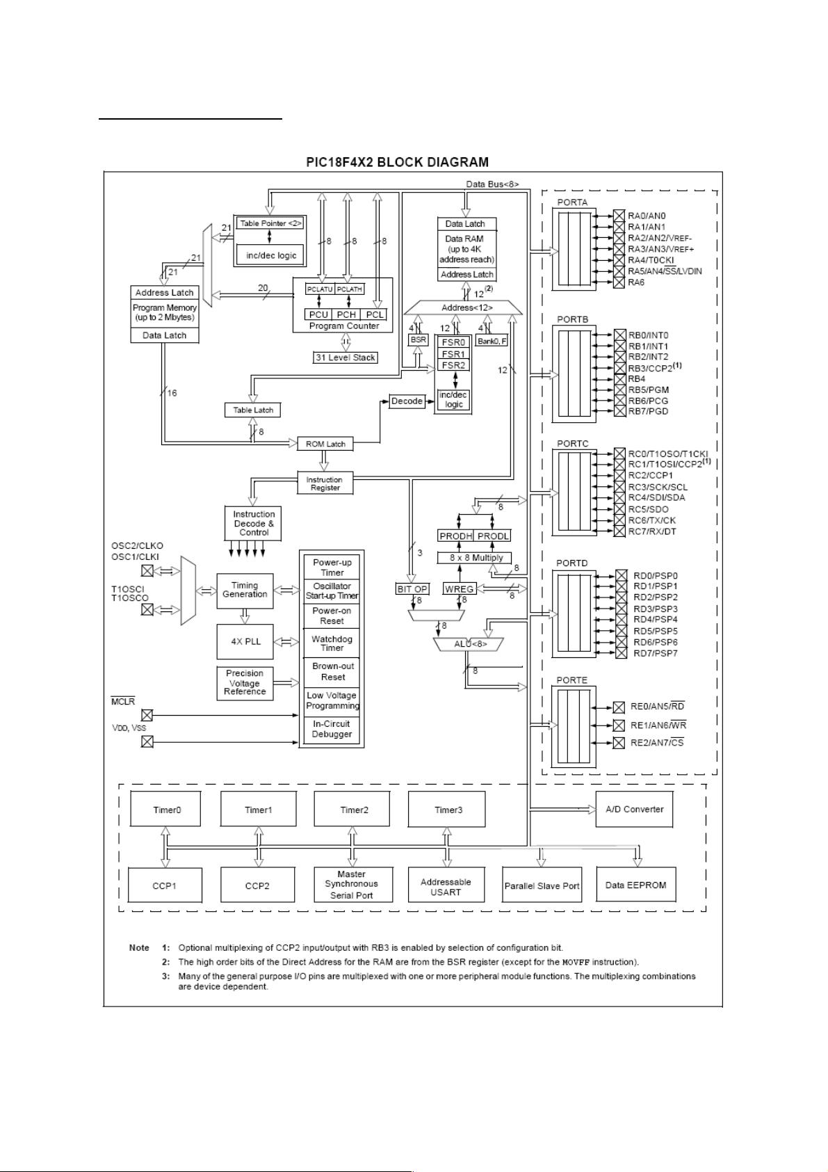
BLOCK DIAGRAM: